Baksi, the friendly bot
 baksa (Icelandic verb): to busy oneself, to do something difficult
Concept
Baksi is the hobby robot that I wanted when I was 15-25 years old.
The design is a result of my frustrations with hobby robots.
Motivation
Here is my experience with hobby robots so far:
The original uArm. My plan was to make it fry doughnuts, but I ended up frying its control board instead. There are two identical power connectors, and you were only supposed to use one of them. And there weren't many programming examples available, so the project stranded.
The Nyrio One. We borrowed this nice 3D printed bot from Karítas in Fab Lab Sauðárkrókur and I had a lot of fun with it.
Then it got stuck in the middle of a move and fried a motor control board. I replaced it and we returned it to Sauðárkrókur. I vowed to make my robot arm incapable of damaging itself!
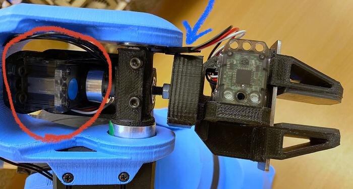 Loose wires connect the gripper to the robot. The connector (marked with a blue arrow) got stuck and the wrist motor (circled in red) released blue smoke.
Skenkir. This was a university project with Guðjón Bergmann and Baldur Björnsson. Our task was to lift a wine glass and give the professor a sip. And because I'm Gyro Gearloose's biggest fan, I wanted the robot to have a hand in a white glove. When the arm bumps into things, the motor control board can overheat so much that it reflows the solder.
Baksi 1 was my first attempt at making a tiny SCARA-type robot arm in the Fab Academy. It has the wrong type of motor control chip.
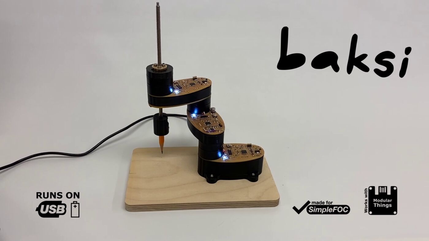
Baksi 2 was my final project in the Fab Academy.
I wanted to make it out of circuit boards and brushless motors and nothing else. But FR1 boards are flimsy, so I had to add 3D printed stiffeners under them.
The bot runs on a single 3A USB-C port, but sometimes it draws too much current and the computer resets the port. That's not good.
Goal for Baksi 3
Baksi 3 will be a RepRap.
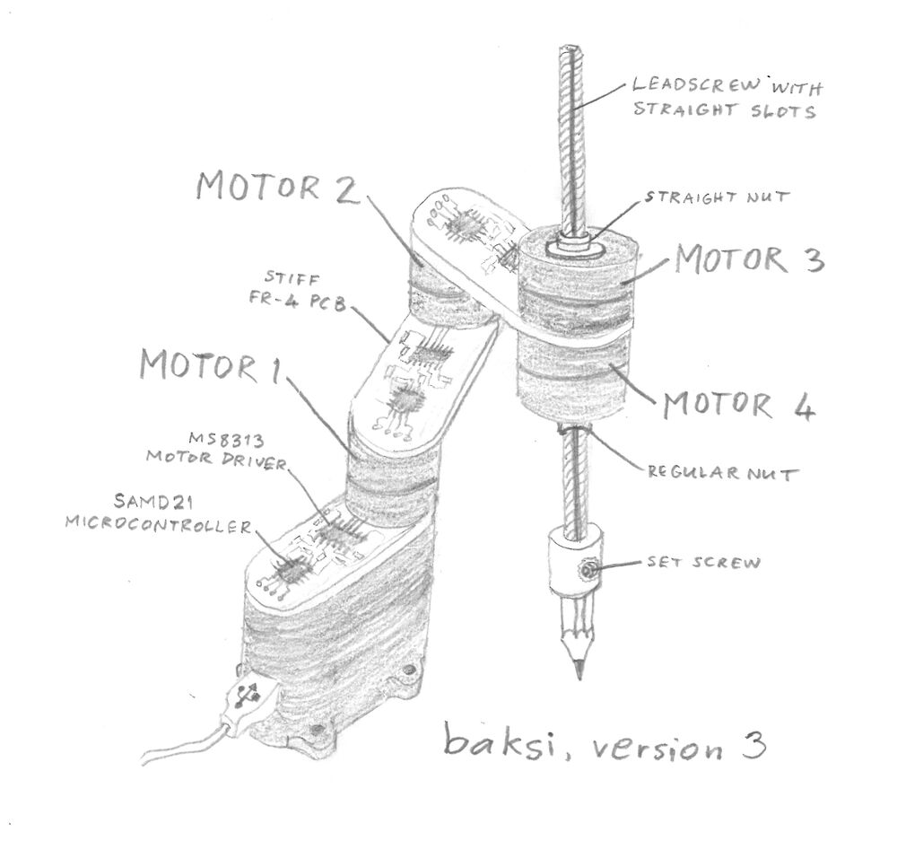
Baksi 3 consists of stiff FR4 circuit boards, brushless motors and the most compact tool changer you've ever seen (and a 3D printed base, because it needs the extra height).
Design criteria for Baksi 3
Educational robot arms don't need to be strong or fast. Here's what I want for Baksi:
- Tiny closed-loop SCARA-type arm made of PCBs
- Cannot hurt itself or the user
- Easily programmed by moving the arm and saving keypoints
- Just accurate and repeatable enough to do useful things
- Changes between two active tools
- Picks up small parts with a vacuum suction cup
- Mills a PCB (badly)
A 3D printing tool comes later.
I know that PCB milling probably won't be very good on such a flimsy bot. But good isn't what I'm going for. The primary goals are a simple construction and self-replication.
Baksi 3 isn't meant as a serious tool; those already exist. The first milled PCBs don't have to look good, they just have to work. Like the prints from the early RepRaps, which were described as 'diabolically bad'. The RepRaps turned out all right.
So what is the point of this bot?
Baksi is meant to be a tiny self-replicating Fab Lab for people who enjoy tinkering with technology for its own sake.
You know, people who like to mod the machine more than they like to use it (like many RepRap, machine tool and robot builders, audiophiles, car modders, retrocomputing enthusiasts, Linux distro hoppers, people who make boats and racing cars but don't drive them, etc.).
Plan
Most urgent
- Make an off-axis angle sensor to make the RZ-axis work (see the off-axis angle sensor page). Depending on how much space the sensor takes up inside the motor base, I may be able to cram a slip ring into the base along with it.
Improvements
- Use stiff FR4 boards instead of flimsy FR1 boards with 3D printed stiffeners
- Replace the DRV8313 BLDC driver with a 5V driver. Then I can get rid of the expensive boost converter in Baksi's base. (FAILED)
- Use Nicholas De Coster's USB Quick Charge hack to power the bot (I've ordered a USB power supply for that)
- Stop using a USB hub in the base of the bot to communicate with each joint separately. Use Jake's mudlink to properly integrate the robot joint modules together. There's also an experimental SimpleFOC I2C library.
- Reduce or remove the GPIO breakout section, I've only used it once on Baksi 2
- Replace the 3.3V, 1A regulator with a tiny 3.3V, 0.1A regulator
- Add a power switch for the motor driver (or do it in software using the motor driver's SLEEP pin). I don't want all the joints to wake up when I'm debugging one of them.
- Remove the RGB status LED
- Add support for a second RZ-axis motor, electrically and mechanically:
- Try to control both RZ-axis motors with one SAMD21
- Make an off-axis angle sensor for each RZ-axis motor
- Remember to put the regular nut on the bottom side of the PCB, so it can pick up tools
- 3D print a passive mechanism for loading and unloading tools
- Implement robot kinematics in Studio Baksi
- Implement path planning in Studio Baksi
Component canditates
Part of the class is to integrate another student's component into your system. I'm considering these components:
- Danny's part positioning guidance system
- Fangzheng's components flipper and KiCAD-machine plugin
- Jake's mudlink for communication between robot joints
- Jens's fabricatable clamp for fixturing
- Lingdong's automatic GUI generator for small displays on machines
- Max's script for generating kinematic mounts for arbitrary (planar) objects
- Nathan's plug-and-play link over Serial for MCU networking
- Nikhil's piezo driver to jet UV resin
- Niklas' Blender as a machine design and programming tool
- Sophia's universal gripper
Future work
- Do I need to protect the USB data lines?
- USB-PD might be a nice addition at some point (something like this ESP project).
- Consider the E3D Revo Roto filament extruder or UV gel for a 3D printing tool
- Enable the bot to move around (see the Mobility concept page)