I modified the holder design.
As the same as week 3/21, when you send 1 2 through serial communication for example, the motor attached to the row 1 rotates twice, which lifts loops on the holders up by 2 pitches.
For another example, 0 -3 means the motor attached to the row 0 rotates 3 times counterclockwise. This moves the loops down for 3 pitches.
It's kind of.. working, but there are things to fix:
From 0:28 in the video above, the motor is stepping out. This looks mainly because the gears got too close to each other due to the tension of the elastic cord.
As to the driven rods (the rods not directly connected to motors), the 3D printed parts rotate arond the shafts and the shafts are supposed to be fixed.
I designed this way because I want to make a bunch of this holder eventually so it needs to be made cheaply.
If I go with the shaft-rotating design, I need to use keyed shafts or D-cut shafts, which makes them expensive, so I didn't want to use them.
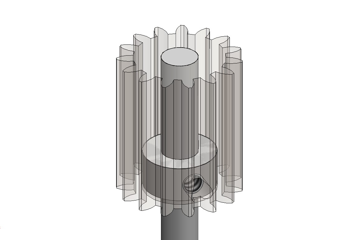
But this design where I used a set screw as a key to fix the 3D printed gear to the shaft for the driving rods worked well.
So I'll probably use this method for the driven rods as well so that the driven rods also can have a shaft-rotating design.
In that case, I can use bearings to fix the driven rods in the X and Y directions; hopefully it'll improve the gear meshing.
As a side note, I can't use this type of shaft collar since they are large and that makes the distance between the rods larger.
At the same time, I probably need to think about changing the 3D printed DIY gears to off-the-shelf gears, or to timing belts.
Decleration also should be considered.
To do:
- Change the driven gear design to the shaft-rotating one
- Test the holder again
- Design the other parts of the machine