We have a LED, a few resistors and capacitors, ATtiny15L microcontroller, a regulator, a zener diode, a serial connection header, and a button/sensor.
+ build an Efe circuit which includes a button and a LED.
+ blink the LED etc.
+ change the circuit geography, use different sensors and buttons
+ fabricate again
+ present the output on the computer screen
 |
A capacitance sensing circuit. |
Check out the light.asm by Raffi for introduction to assembler. It includes commenting in code, setting constants, including definition files, jumping in the code, looping, turning on and off the pins, creating a delay, dissecting a delay, and finally they come together and flash the LED.
Here is some basic assembly code. ";" is a comment, "." is an assembler directive, ".include" inserts another file, see more definitions as comments in the code:
; this is a comment for human beings and does nothing .include "tn15def.inc" .cseg ; start code segment .org 0 ; position at address 0 rjmp main ; reset handler ; some code main: ; reset label ; some more code |
We have ready-made assembler and python codes:
+ serial output (hello.efe.asm)
+ blink the LED (efe.blink.asm)
+ measure charging (efe.charge.asm)
+ plot charging (efe.charge.py)
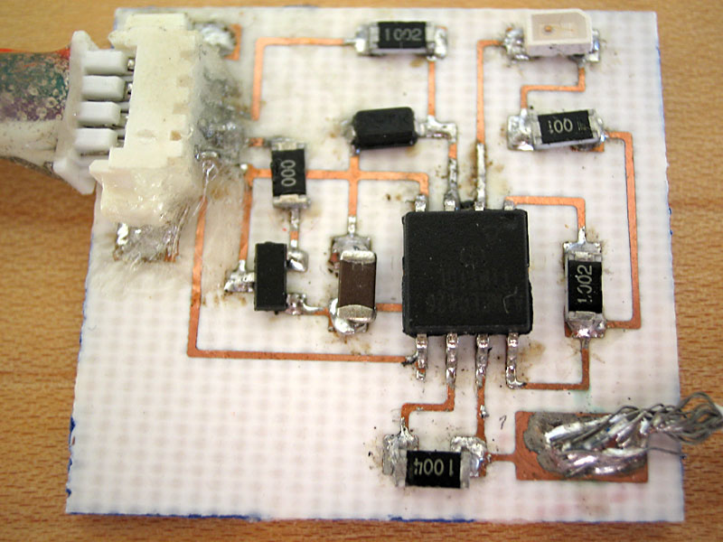
Schematic and PCB of the Efe circuit:
 |
Using a 0 ohm resistor instead of a jumper (eg. the green area) is a quick and economic way. |
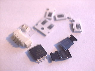 |
Parts for the Efe circuit. This ATtiny15L microcontroller itself has: + 1K byte of Flash, + 64 bytes EEPROM, + 6 general purpose I/O lines, + 32 general purpose working registers, + two 8-bit Timer/Counters, + one PWM output, + internal Oscillators, + internal and external interrupts, + programmable Watchdog Timer, + 4-channel 10-bit Analog to Digital Converter, + 3 software scalable power-saving modes. wow, it's a lot! |
Check out Handbook of Modern Sensors by Jacob Fraden.
Check out the wisdom by cutting guru Zach for rapid board fabrication.