We use a stepper motor that moves in series of steps, and digitally geared. It is controlled by 4 magnetic coils and 6 magnets mounted in the shaft. It is controlled by giving current to the coils. It creates a magnetic field and attracts the magnets, so the motor rotates. Current control is the key attribute of stepper motor control. It has two types; unipolar and bipolar (HBridge). Bipolar has twice the magnetic filed strength, so twice the torque. But it has 4 NFET transistors. Uniploar has only two NFET transistors, and has less torque.
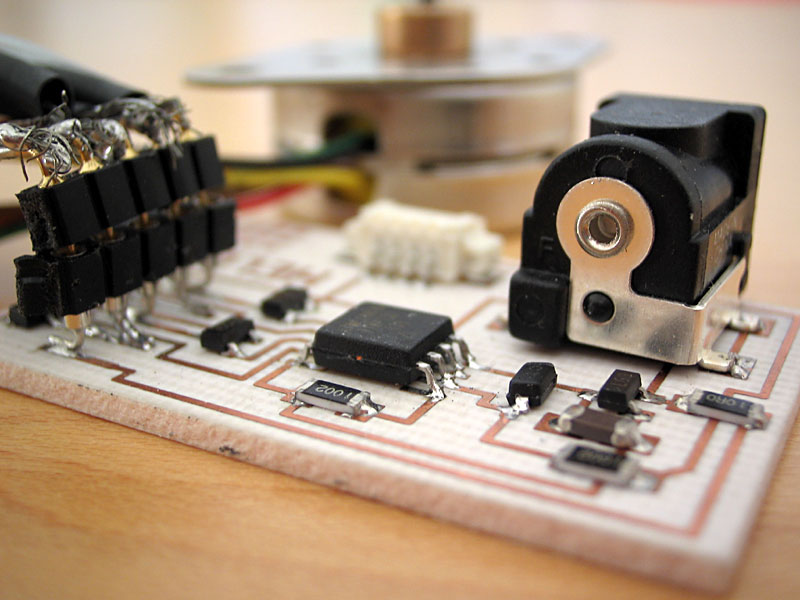 |
A stepper motor control circuit consist of an ATtiny 15, 4 mosfet switches, an external DC voltage, a regulator, some resistors, a capacitor, a zener diode, and a header for serial connection. |
Make sure the power gets dissipated in motor, not in the circuit.
In addition to the stepper motor, we have four MOSFET switches, ATtiny15L microcontroller, two 10k resistors, a 10 ohm resistor, a capacitor, a regulator, a zener diode, a header for the motor, and a DC input.
Micro stepping: steps smaller then a step, it is for synchronizing the microtime of microcontroller and the motor response.
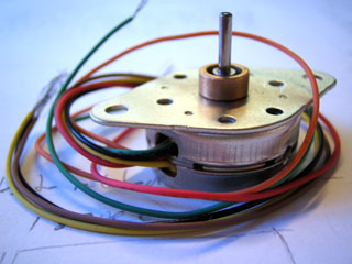 |
A stepper motor. The cables coming out of the motor are usually standart. The Red and the green are supply voltages, the others are logic inputs. |