Week06 - Embedded Programming
This week was a little more straightforward. Alter the "helloFTDI" board design to add a button and LED. Below is the design I arrived at in Eagle, a board design, routing, and schematic application. Neil pointed out as I was milling that I didn't really need the 10K "pull up" resistor prior to the button as the pin I'd be attaching to on the micro controller had this function built in, as the datasheet indicated (you all READ the datasheet, right?).
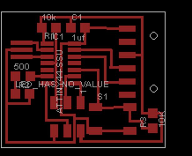
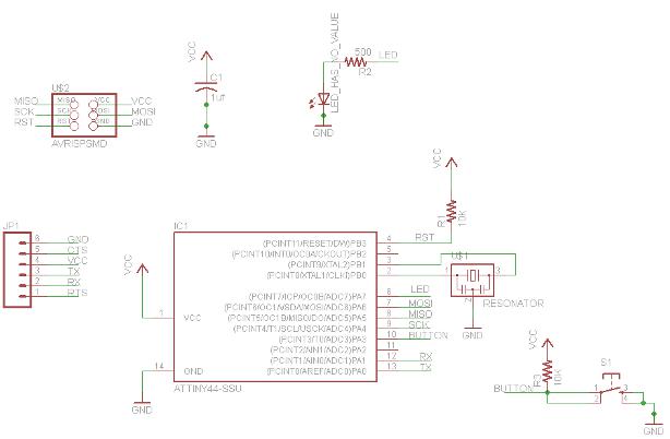
The difference between the schematic and the actual board layout. The schematic view will generate a "bill of materials" so you have a shopping list when you go to pull parts. Very handy.
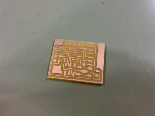
A freshly milled board. Altering the dimension of the FTDI with the unnecessary 10K pull up means the FTDI header doesn't line up exactly with the edge of the board. Luckily it wasn't that far off and I had no trouble mounting my cable.
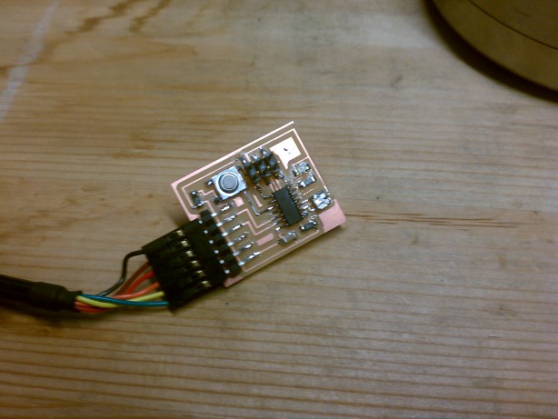
Fully stuffed and ready to be programmed with the FabISP board we built a few weeks ago. The FTDI is on backwards in this photo. Black should run to GND. One small mistake is I soldered a 4R99 resistor prior to the LED rather than a 4990 resistor, which means my LED would have been very bright and very short lived. No issues were encountered desoldering and replacing the correct resistor prior to programming.
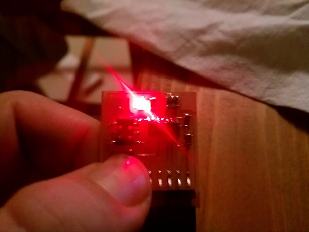
And here's the proof in the pudding. It lights up beautifully when the button is pressed. You may bask in its warm glow.
I call it my "self esteem button" and press it whenever I need to feel better about myself. It is magical. By the way, I thought I'd put on a GREEN LED, but it turned out red. Others also encountered this and I'm wondering if someone switched the rolls down in 043?
Currently working on creating a board with meaningless blink lights to take to the Salem Ghost Tour, as they claim to be "paranormal investigators" whose gear seems to include a flashlight and a stud finder.
So, until next time then, Space Cadets! NovySan, OUT!