Note
Further revisions to this project will appear in the project archive's Fab Boombox page.
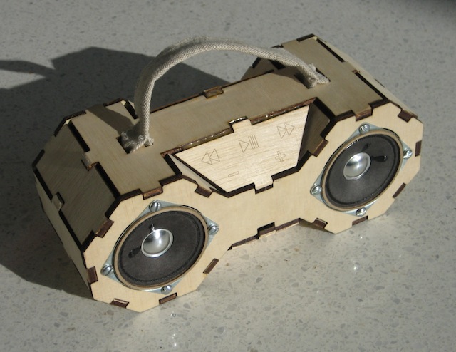
Concept

This is a boombox made with the tools and techniques common to fab labs. It plays music off of a standard SD card, runs on a single 9V battery, and can be fabricated for under $100.
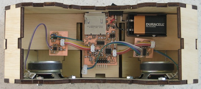
Control Board
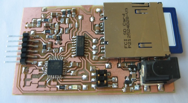
The main control board includes at Atmega328, an SD card socket, an mp3 decoder + D/A chip, and a level shifter to convert from 5V to the 3.3V required for the SD card and mp3 decoder.
The board was designed in Eagle as a two-sided PCB. It was manufactured on the Modela. Since the board was symmetric, it could be flipped over and replaced in its original cavity after being cut out - this allowed for easy registration between the two sides.
Vias were manufactured with the following procedure:
- Cut a small amount of solid wire
- Fold into a right angle
- Insert into board with angle resting on the top surface
- Solder in place
- Flip board over
- Solder protruding pin
- Cut off ends
This technique prevents the via wire from escaping, since the angle holds it in place against the table.
Top:
Bottom:
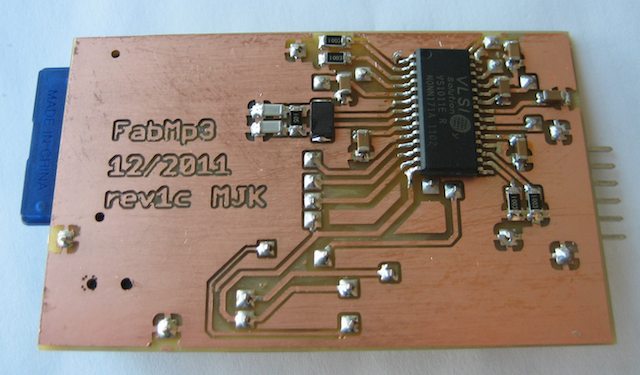
The main board's firmware was written in the Arduino language to take advantage of the SD library. Some of the code is based on the Sparkfun MP3 shield sample code.
Input System
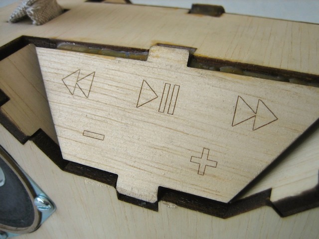
The boombox has a set of five capacitive buttons on the front. Each of these buttons is above a copper pad, which is in turn wired into the input board.
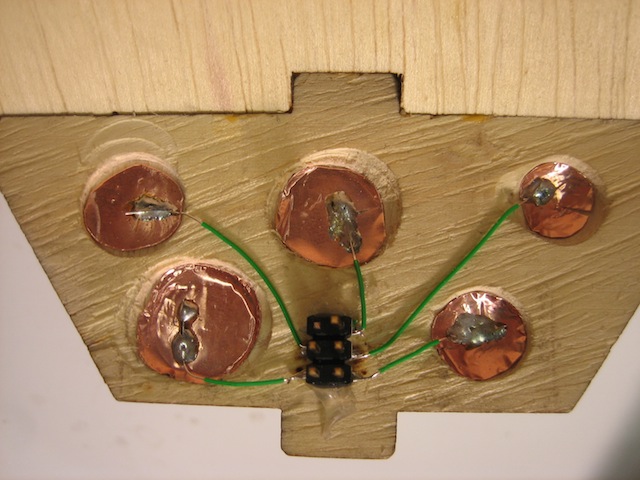
The input board charges each copper pad through a 10 MOhm resistor. The change/discharge curve is sampled going up and down, and the values are subtracted to eliminate noise. Each pad is sampled 50 times then compares against known thresholds to determine if the button has been pressed or not.
I spent a while fine-tuning both the thresholds and the delay time in between changing the pin and sampling the value with the ADC; picking this delay time correctly improved the sensitivity of the device. Still, this is the least successful part of the project - the thresholds are variable depending on how wires end up inside the board, so it only works part of the time.
When buttons are pressed, the input board sends data back to the control board through a homebrew one-way protocol. It lowers a pin to indicate that it has data to send, then the master clocks data it when it has spare time.
Audio Amplification
There isn't much new work here - I borrowed the circuitry from David Mellis's fab speakers, though I did re-layout the board to shrink it down. Output from the mp3 decoder's DAC is run through a set of analog circuitry on the main board, then piped into a pair of standard audio amps and out to the speakers.
Case
The case is a retro-inspired set of nested octahedral prisms.
It was designed in the fab modules, so it is fully parametric. This made prototyping out of cardboard easy, because I just had to change the material thickness variable then rebuild the parts.
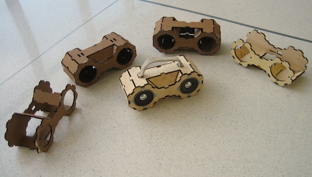
The final case was fabricated on a laser cutter from 0.208" wood. The snap fits were all just fine, and the whole thing mostly stays together without glue. A few of the diagonal pieces are glued in place for security.
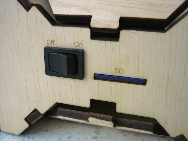
The three PCBs are hot-glued onto standoffs that are in turn screwed into the inner shelf of the case. The battery case is screwed into the inner shelf and the power switch snap-fit through the outer wall then soldered in-place.
A handled made of scrap cloth is sewed onto the top panel. Since this panel is press-fit, there's also a rope running under the top panel to lock it in place (or at least prevent it from completely falling off).
Slots on the back allow easy access to the SD card and power switch.
Source
Eagle files:
Main board
Input board
Amp board
Libraries
All of these folders include a Makefile that creates board images, including automatically cutting out vias in the cutout image. These makefiles require PIL to operate.
Firmware:
Main board (Arduino project)
Input board (C source and Makefile)
Case:
Source
Requires the fab modules. Automatically compile all of the parts with the included Makefile.
Acknowlegments
- Neil, for obvious reasons.
- John and Tom, for making everything possible.
- Sparkfun for great example code.
- David Mellis for speaker design.