Final Project Development
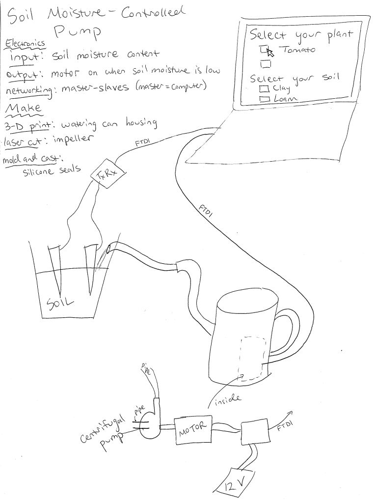
For my final project, I am making a pump that automatically turns on to water plants when soil moisture content becomes low. I am using a computer to control the devices. The input, the soil moisture sensor, will send capacitance data to the program, which will determine if the capacitance rises high enough to indicate a lack of water; if the capacitance passes the threshold, the program will tell the output device, a motor, to turn on. This motor will drive a pump. When the moisture levels rise again, the program will tell the motor to turn off.
Parts and Systems
- Soil moisture sensor
- Pump
- Motor
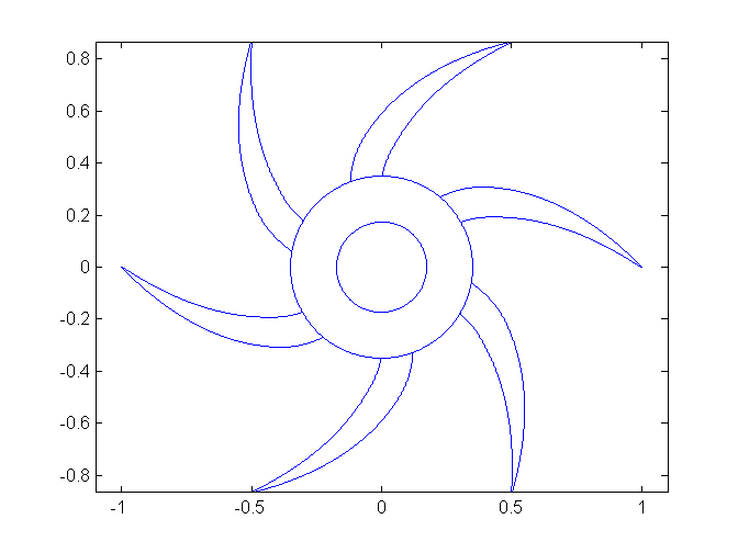
- Impeller
- O-ring
- Shaft seal
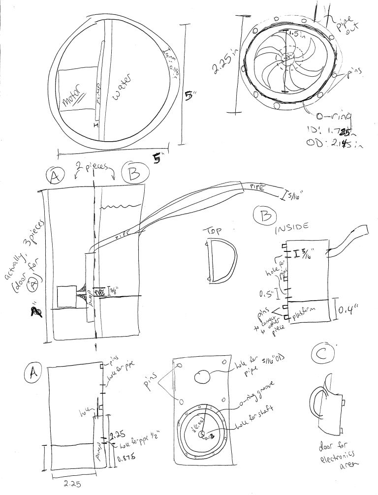
- Housing, shaped like a watering can
- Piping
I am applying the following class skills:
Electronics
Input device: soil moisture sensor
Output device: motor
Networking: master-slave
GUI: the user selects the plant and soil type in order to determine the necessary soil moisture levels
Making Processes
Modela desktop milling: electronics
3-D printing: pump housing shaped like a watering can
Laser cutting: acrylic impeller
Molding and casting: silicone seals, such as o-rings
The Bill of Materials is as follows:
| Vendor | Product # | Part | Cost Per Item | Quantity | Total Cost | Already in Lab? |
| Jameco | 253471 | DC motor, gear 50:1, 12V, 120 RPM, 1100G-CM, 74MA | 13.45 | 1 | 13.45 | yes |
| McMaster | 9562K41 | Stretch-Fit Rotary-Shaft Ring Seal, 1/4" Diameter | 3.52 | 2 | 7.04 | no |
| McMaster | 9557K305 | EPDM O-rings, 1 3/4" ID (10/package) | 4.28 | 1 | 4.28 | no |
| McMaster | 5233K63 | Masterkleer PVC tubing, 3/8" ID, 1/2" OD | 0.29/ft | 25 ft (smallest available) | 7.25 | no |
| McMaster | 8560K163 | Acrylic Sheet 3/16" Thick, 6" x 12" | 5.84 | 1 | 5.84 | no |
| Total (not in lab) | $24.41 | |||||
Note: I have included o-rings and shaft seals here just in case my own casted silicone seals fail.
Progress
So far, I have been focusing on planning, designing, and CADing the components for my project. I already made my soil moisture sensor in an earlier week (you can see it here), CADed my motor-with-FTDI board in Eagle (though I have not milled or stuffed it), and CADed my impeller and half of my pump housing.
I've had a lot of difficulty transferring the MATLAB plot of my impeller into SolidWorks, and I still have been unable to extrude it. However, I decided not to worry about that, since I only need a 2-D image to laser-cut the impeller out of acrylic. I moved the MATLAB plot to SolidWorks via Illustrator (I was able to save the MATLAB figure as a .eps, open that in Ilustrator, then save it as a .dxf and open it in SolidWorks).
My schedule to finish the project is as follows:
Wednesday: finish all remaining CAD, laser-cut acrylic impeller, send pump housing to 3-D printer
Thursday: mill and stuff motor board, mold and cast silicone seals
Friday: assemble all the pieces, program the input and output devices
Saturday: program the GUI
Sunday: catch up on whatever I couldn't complete on time; debug
Monday:
debug, debug, debug!
Questions Remaining
How do I know when soil moisture is considered low?
How much water should be added to the soil?
The USDA has some guidelines about moisture levels and water application, but I need to figure out how to translate that into capacitance. I'm still on the hunt for a research paper that has already done this.
Evaluation
I will consider this project successful if it actually works! That is, if the pump actually does water soil when it is determined to be dry, and then shuts off when there is enough moisture. The tricky part is finding dry soil, since most plant shops sell soil that is already prepared for plants.