Final Project
This week I made a quadcopter. I designed a frame and cut it from aluminum on the waterjet, then added brushless motors and controlled them with a bluetooth microcontroller using readings from an IMU.
Motors and Speed Controllers
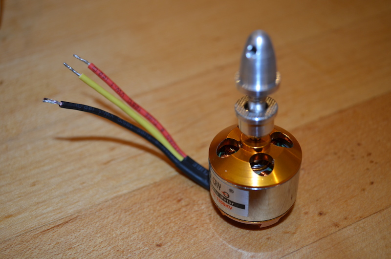
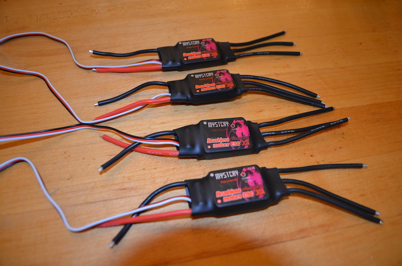
I purchased four sensorsless brushless DC motors from Amazon. The motors come with mounting backets and caps for propellers. I considered making my own electronic speed controllers but time considerations prompted me to buy them instead. The controllers I got off Amazon accept a basic servo signal, a 50 kHz PWM signal where a 1000us pulse corresponds to 0% thrust and a 2000us pulse corresponds to 100% thrust.
IMU
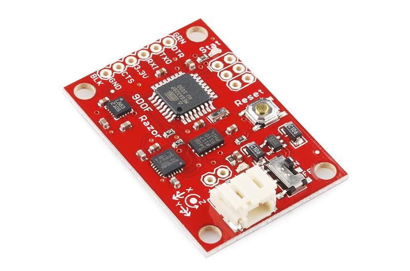
I bought an IMU from SparkFun that has an ATMega328 to read from an accelerometer, gyro, and magnetometer over I2C and report the sensor values over Serial. The ATMega328 performs a sensor fusion from the nine degrees of freedom to produce three values: yaw, pitch, and roll.
Frame
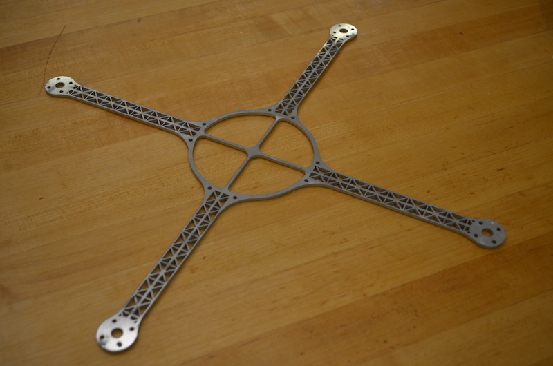
I designed the frame in Solidworks. I went through several designs and considered both 3D printing and a waterjetting design but ultimately chose to waterjet because it is so much faster. I included as many cutouts as possible in the frame design to make it light. In the end, using 1/8" 6061 aluminum, the entire frame weighed only 60 grams, the same weight as just one of the motors. Not bad! I had to cut the frame twice because the first time I mismeasured the drill holes on the under side of the motors. I assumed that they would all be equidistant and measured just one distance but the two sets of holes are actually different distances from the center. I updated the design to use the included mounting brackets and also made the center larger to accommodate a larger battery.
Control Algorithm
Next I wrote a sketch for the RFduino I used in Networking Week to control the ESCs. The RFduino doesn't support the software serial library so I had to use the UART to read from the IMU, which made debugging and programming a pain. The serial stream is binary encoded floating point numbers representing the yaw, pitch, and roll of the board. I used a union in C to unpack each set of bytes from the IMU into a float.
float bytesToFloat(char *d) {
  union {
    char c[4];
    float f;
  } u;
  u.c[0] = (uint8_t)d[0];
  u.c[1] = (uint8_t)d[1];
  u.c[2] = (uint8_t)d[2];
  u.c[3] = (uint8_t)d[3];
  return u.f;
}
Next I wrote a proportional control loop. I computed the difference between the observed and desired yaw, pitch, and roll, then adjusted the throttle on each motor. To be able to tune the gains I made them adjustable from my laptop via bluetooth, in addition to the throttle.
float dyaw = (desiredYaw - yaw) * yawGain;
float dpitch = (desiredPitch - pitch) * pitchGain;
float droll = (desiredRoll - roll) * rollGain;

if (throttle == 0)
    motorsOff();
else {
    motors[left].writeMicroseconds(mapf(throttle - droll - dyaw, 0.0, 1.0, 1200, 2000));
    motors[right].writeMicroseconds(mapf(throttle + droll - dyaw, 0.0, 1.0, 1200, 2000));
    motors[front].writeMicroseconds(mapf(throttle - dpitch + dyaw, 0.0, 1.0, 1200, 2000));
    motors[back].writeMicroseconds(mapf(throttle + dpitch + dyaw, 0.0, 1.0, 1200, 2000));
}
The control loop operates the quadcopter in a 'T' configuration, where the front and back motor control the pitch and the left and right motors control the roll. Two opposing motors are always adjusted up and down equally to maintain overall throttle.
Conclusion
In the end, the quadcopter just barely was able to take off and fly and had very poor control of yaw. I spent most of the project working on the mechanical design and getting the electronics running and left very little time for working on the control algorithms which proved to be by far the hardest part.