Sam Spaulding
How to Make (almost) Anything
Week 3: Printed Circuit Boards - Fab ISP: an in-system programmer for microcontroller devices
"In theory there's no difference between theory and practice. In practice, there is."
- Unknown
Phase I: Cut it Up!
Our assignment this week was to learn how to use the Modela mill to cut a Circuit Board (not actually 'printed' but we're still calling them PCBs), stuff it with components (a microcontroller, USB connector, and various other connecting components), and program the micro-controller in order to enable it to then program other controllers. Sound complicated? It's actually fairly straightforward.
The first step is using the mill to cut out the traces of your board. It's easy to use in theory: place you copper board, load up the trace file, and send it off to the mill. In practice, there are a whole bunch of different variable that need to be checked up on, and any one of them can result in a poorly milled board. Trust me. I know. Because I made three different boards that didn't work before I got one that milled properly. And then I proceeded to destroy that one with the mill while cutting it out. And then, finally, I got one that I could use.
In all seriousness, using the Modela was actually quite a learning experience. Unlike the laser cutter, which pretty much just works without much tweaking, the Modela can be quite fickle. Thus I've compiled a quick checklist of things to look out for when milling a PCB:
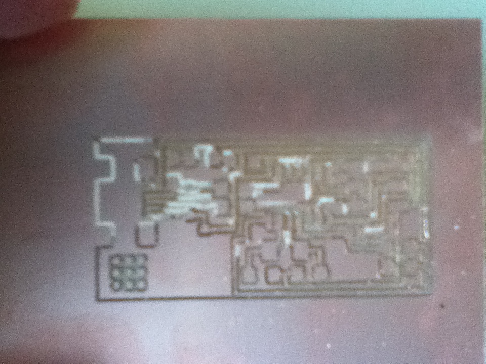
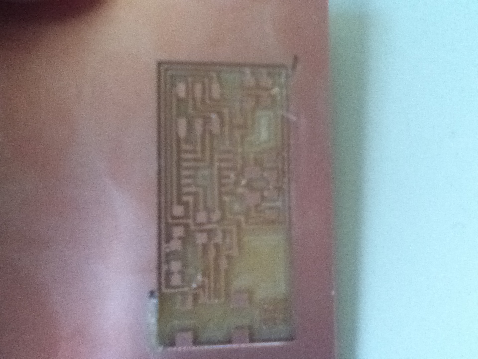
1) Place your copper sheet on the mill board with double-stick tape, making sure there is a sacrificial layer underneath. Try to find the flattest possible place, otherwise parts of your board will cut out properly, but others will not - making it looks like this.
2) Load up your png, set your endmill setting to 1/64th. The defaults here are actually pretty good: -.12mm for the Zmax and 3.5mm/s for the speed
3) Actually make sure you have the 1/64th endmill in the machine! If not, swap it out carefully while not in view mode and use the xmin/ymin settings to move the mill to the origin.
4) Calibrate the Zmin setting. Essentially, you need to slightly loosen the endmill so that it sits directly upon the copper sheet. Once it's resting, tighten it back into the mill. Make sure that a) the endmill is still gripped tightly by the bit holder and b) there is still room for the bit holder to go further down into the copper. These two goals can be slightly at odds with each other - leading to boards that either aren't sharp looking (because the grip was too weak) or barely milled (because the bit didn't have any more room to drill down after setting the Zmin)
5) Send your trace job off!
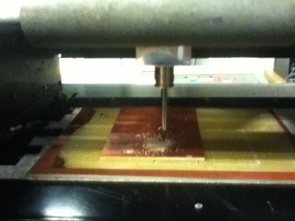
Assuming everything goes well, you'll now want to cut the board out. Go through the process of switching out the drill bits, this time you'll want a 1/32"" bit. Load up the outline of your board, follow steps 1-5 again and cut it out. TA DA! You should now have a nicely milled circuit board!
Phase II: Stuffing the Board
Now that you've got a nice, clean board with traces on it, soldering componenets come next. Luckily, soldering is much less of a black art than futzing with finicky machines, and some helpful pointers helped me escape with only a few singed fingers
1) Start by melting a little bit of solder onto one pad per component - you'll use this to fix them into place
2) Heat the soldered pad a bit, then drop the component onto it with the tweezers
3) Finally, add a bit of solder to the connecting pad, then wick away any excess from either side.
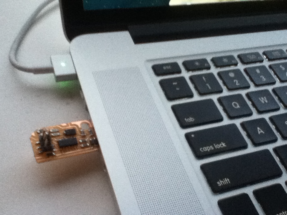
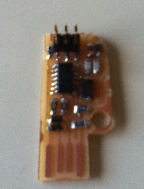
After a couple tries and cleaning up a bit, I finally had a completed, stuffed board!
Phase III: Programming for Programming
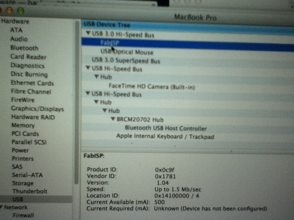
This has been the first bit of "programming" in the course. And really it just involves downloading some packages, and running a couple shell scripts to install the firmware onto the ATTiny44 chip on the board. Following Neil's instructions online was pretty straightforward. And then....boom! The computer recognizes my AVR Programmer!