Measure something: add a sensor to a microcontroller board that you have designed and read it.
This week I wanted to continue with my design for my grown-up lite brite and see if I could get the capacitive touch working.
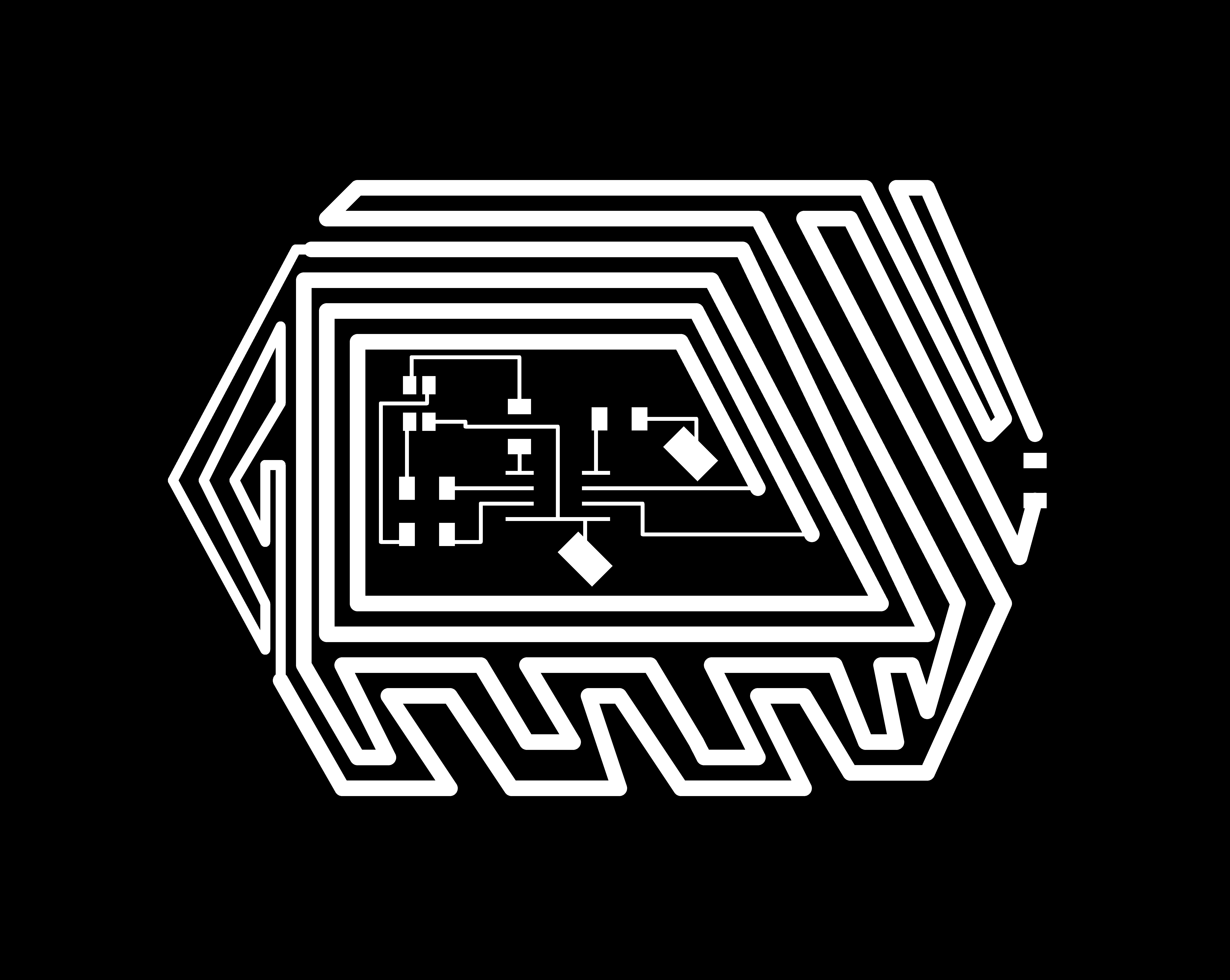
I really wanted to get a good sample board done this week so that I could get all of the kinks worked out and mill the hundred plus boards needed for my final project over Thanksgiving. The circuit boards for my hexagon were going to be 2"x3" so I decided to design the outline in the hexagon shape, with traces filling the rest of the board, so that the user would be able to touch anywhere on the board and activate the LED. Additionally, at this point, I was still under the illusion that pogo pins were my friend. Past tense.
With this board, I did end up drilling holes for pogo pins. However, again, the holes ended up way too large, resulting in a giant solder mess. Once I actually got them stable, I attempted to use a hot glue gun to keep them in place for programming. Still not great. At this point, I decided that for the sake of time, as my holes were way to large, I would just solder wire to my ground and VCC.
To make this work, when routing the board in Eagle, on the dimension layer I needed to design two holes that lined up with the pads that I set for ground and vcc.

Milling this board took approximately 38 minutes, which is way too long if I am going to mill 100+ boards. Special TA friend Sam came up with the brilliant idea to mill the entire board with the 1/32 end mill instead of the 1/64. However, to do this, I needed to create a new footprint for my ATTiny45 and my RGB LED.

In addition to changing the traces for the endmill, I decided to go ahead and make the board slightly larger as well. We have several long sheets of 3" circuit board stock in the basement, and Smart Friend Sam suggested that I feed those through. By having a bigger board I would be able to make less circuit boards in the end.
Because this was a test, I decided that I would figure out the pogo pins (or an alternate option of copper nails) later and would just solder wire to my VCC and ground pads for programming. Milling only the traces with the 1/32 worked well and only took 12 minutes.

To make mass production faster, instead of using an ISP header on each board, Special TA friend Sam, Will, and Prashant, advised that I use a programming clip that will clip to the microcontroller. Then, using male and female cables, connected it to the programmer. My board didn't instantly program. Groan. After pulling out the multimeter, Prashant and I discovered that there were some wobbly connections. Tried again. Still no luck. Darn it!!!!!!!!!!!!!!!!

So 45 minutes later I discovered I did something super silly when designing my board, which Neil probably noticed right away- I connected my VCC and Reset pin. Whoops. After pulling up the copper the board programmed.
I used Neil's transmit-receive code to program my board. Which totally worked. The touch sensor worked, but when I tried putting acrylic over it, the sensitivity wasn't strong enough to work through the acrylic. So, while the touch sensor does work, it won't work for my final project. So, I will now be redesigning my board with thicker traces.