Philippe Parreno / Anywhere, Anywhere Out of the World
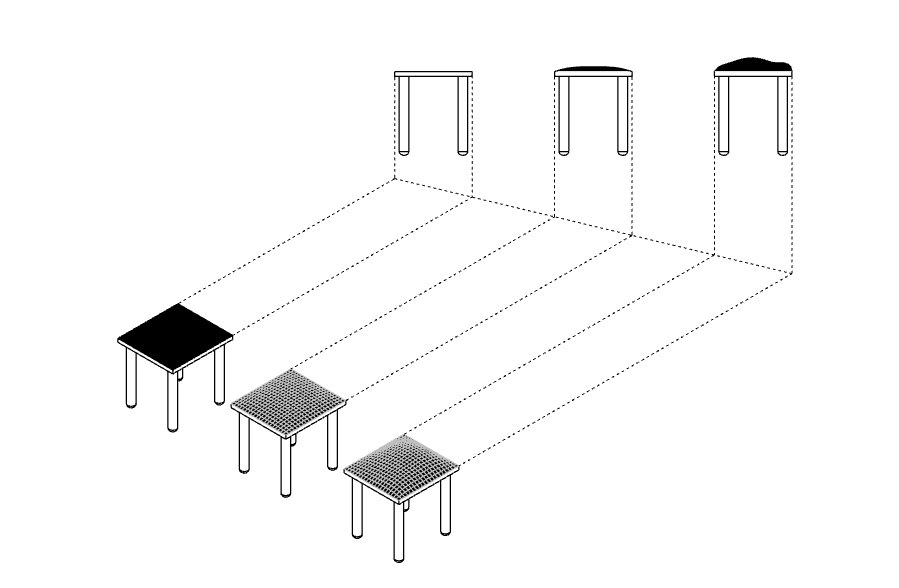
For my final project, I'm thinking of creating a set of objects with some (minimal) agency that would upset / reset / defamiliarize our daily experience. They could be cast or CNC'd or made out of some soft material (think pillow), and they would all exhibit some form of disembodied human behaviour, such as breathing, humming, or hugging. I would achieve this by making them appear like an anthropomorphic lamp, chair, or other everyday object, but encode some simple behaviour (e.g. dimming at the pace of breath) that would place them in the interstitial space between objects and agents.
Breathing chair
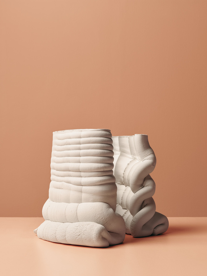
Jes Fan's "Poke"
Jes Fan's "Forniphilia I"
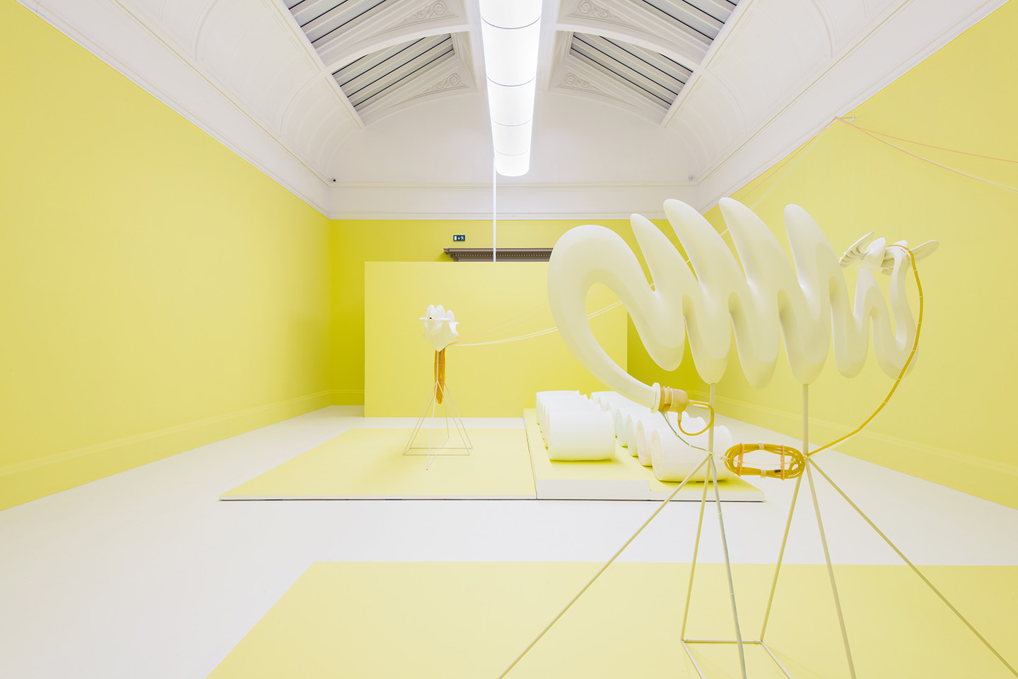
Marguerite Humeau's "Echoes"
#2: Disobedient ceramics
Anton Alvarez's Alphabet Aerobics
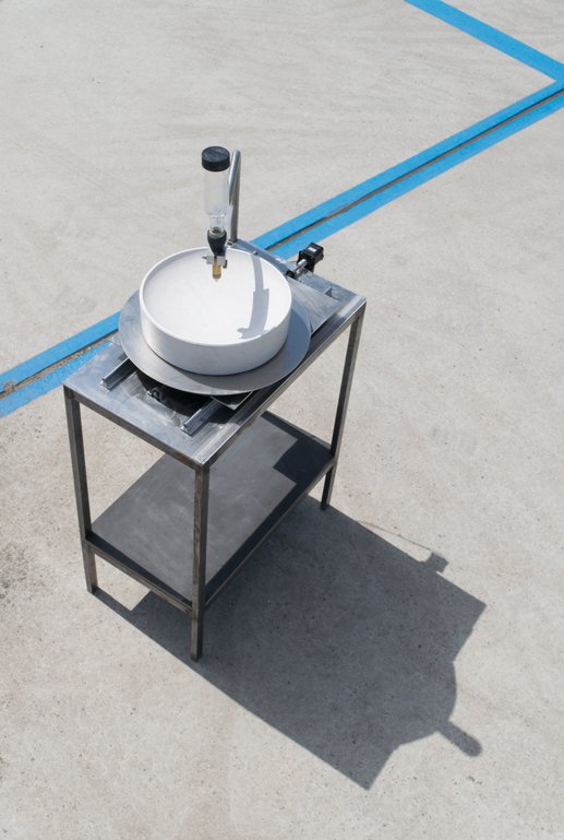
Jung and I decided to re-focus our intentions and bring together 'drawing' and 'objects' by creating a ceramic dripper that intergrates a mechanical valve, a rotating base or a Stewart platform, and slip casting, inspired by Studio Joachim Morineau's Moca Machine.
Moca Machine by Studio Joachim Morineau
Studio Joachim Morineau's dripped and slipped ceramics
Studio Joachim Morineau produced some beautiful ceramic cups and bowls using a dripper end that drops liquid clay ("slip") onto a plaster mold, and is then easily extracted from it. We envied the forms (integrating intentions and stochastic flow, hand-designed parts and machine autonomy) and wanted to produce something similar.
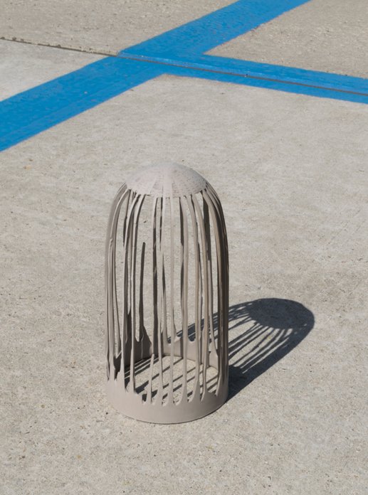
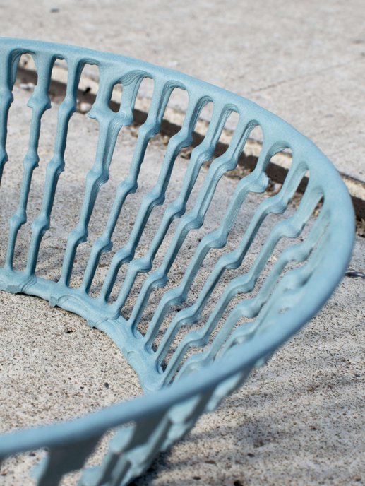
Autonomous, standing structured dripped by Studio Joachim Morineau
What does it do?
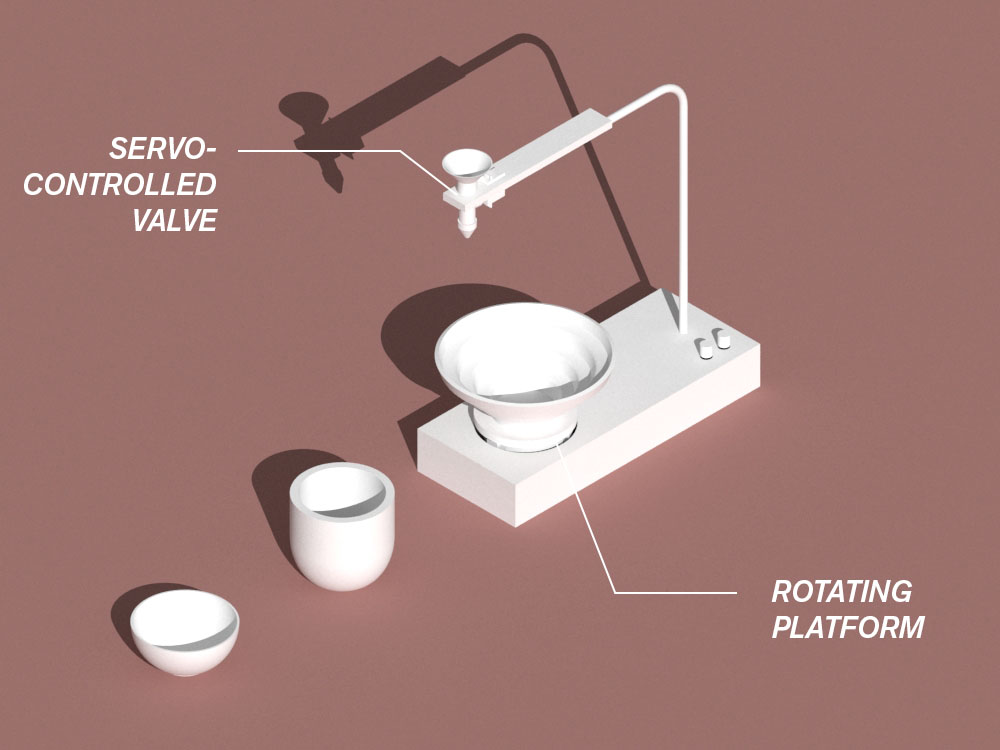
The project is a slip-casting machine that makes open structures by dripping slip (liquid clay) onto a cast plaster form. It creates a 3-dimensional drawing by tracing the path of slip (clay) on the plaster surface. It can drip at different rates (the part that I worked on) and rotate the base plate at different speeds (the part that Jung worked on). The project integrates 3D design and fabrication (milling, casting, waterjetting, 3D printing), electronics design (the servo, stepper, and input elements), and interfacing (the PCB's working together, connected in a Serial bus).
Who's done what beforehand?
The Eindhoven-based Studio Joachim-Morineau created the object that we wanted to learn from; and we attempted to reproduce its functionality as well as expand it.
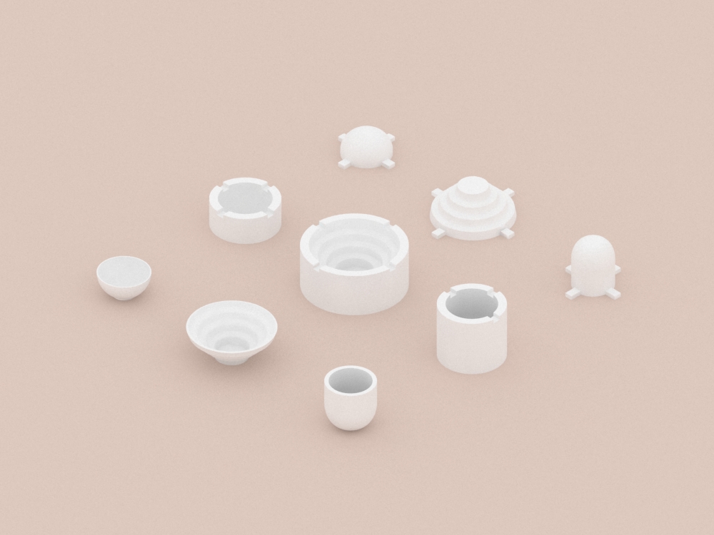
What did you design?
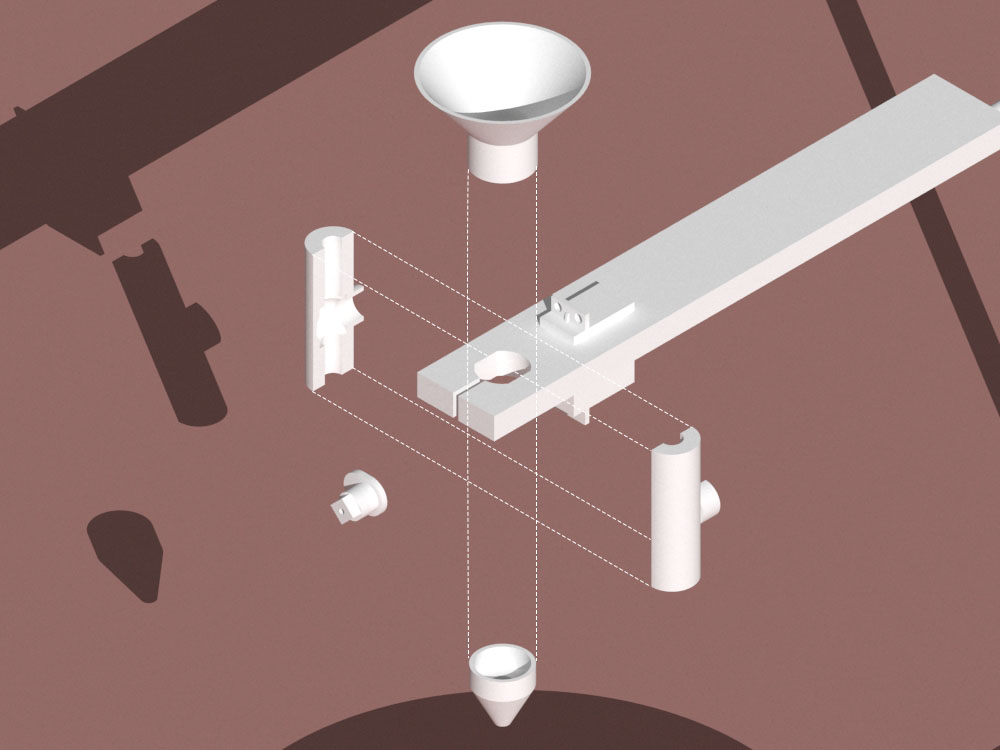
I made designs for the milled foam formwork for casting the plaster bowls; the 3D-printed valve with a connection to the bottle and different nozzles for modulating the drips; the acrylic holder and the bent metal arm.
What materials and components were used? Where did they come from? How much did they cost?
We recycled (scrap) plywood, aluminum, 1/2" acrylic (which had to be waterjet), and we bought a steel rod for $14. We used filament and plaster from the ACT and Architecture shops (many many thanks to Graham for ordering the clay for us and teaching us how to cast!). The clay was $12 per bottle and we only used about 1/4 of a bottle for all the testing, since you can always recycle the leftover liquid clay. We used the electronics from the shop, but we bought potentiometers for ~$5.
What parts and systems were made?
We independently worked on two systems / parts and integrated them into one larger system at the end: I worked on the dripping (designing the PCB for the servo, debugging, connecting to main board and taking the input; designing the valve with multiple iterations for its size, the nozzle, the connection to the bottle; designing the objects to drip to and the arm to hold up the servo and valve.), and Jung worked on the rotation and the base (the PCB for the stepper, connecting to main board, rotating at different speeds, making the stand with bearings for a smooth and effective rotation; designing the case for the arm, the motor, and the inputs). We both worked on integrating the boards and communicating to them from the master board.
What processes were used?
We milled, waterjet, cast (with plaster and with slip), 3D-printed, bent metal, manufactured and programmed PCB's to create both output and input devices, as well as network them.
What questions were answered?
How was it evaluated?
What are the implications?
The ceramic drawing machine was an experiment in architectural drawing and form-finding. We wanted to learn from Studio Joachim-Morineau's fantastic work and see if we could integrate the skills of HTM(A)A in this machine that makes--and find whimsical structures that generate new avenues of design.
Our design for the machine
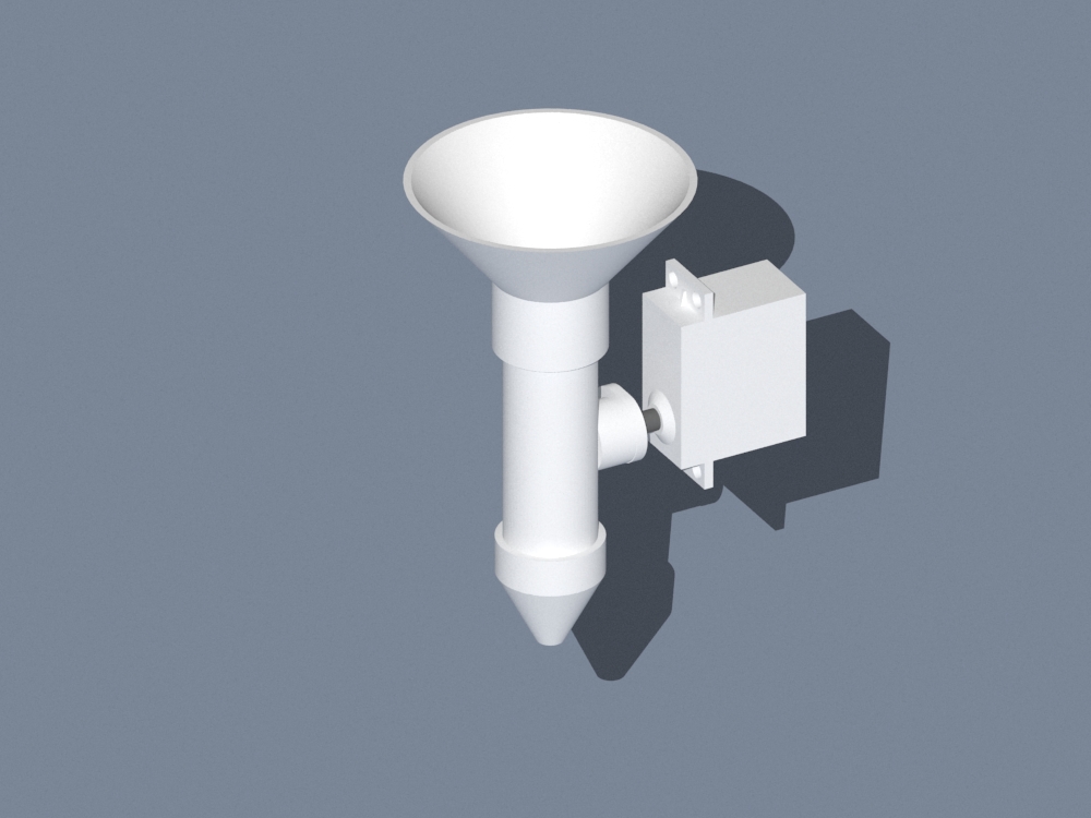
Valve design
Valve design
Valve design
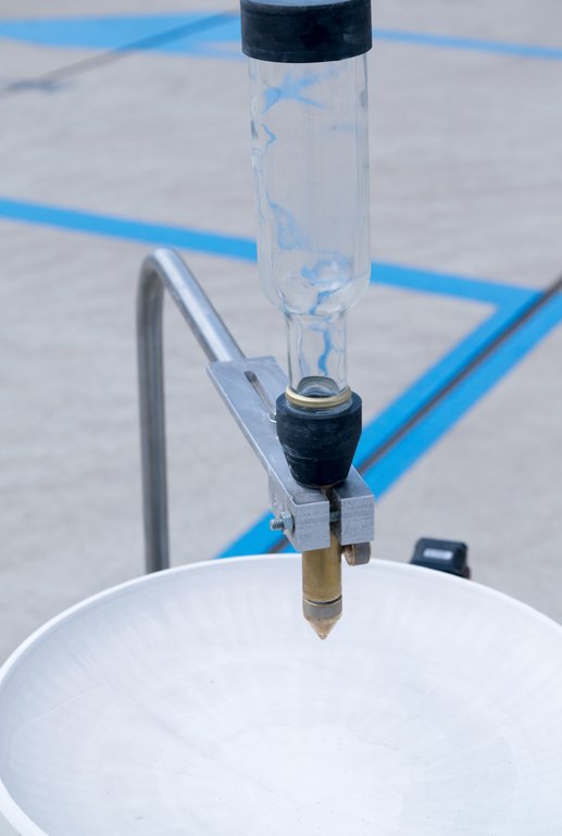
Dripping!
Design for the Servo-driven valve
Electronics
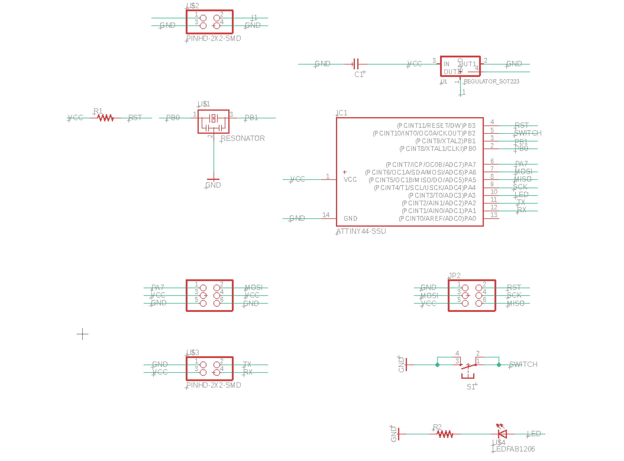
Eagle schematic for the servo
I started by designing the servo board and putting together a draft for the main controller that we both needed. For the servo, I integrated a switch and an LED for debugging.
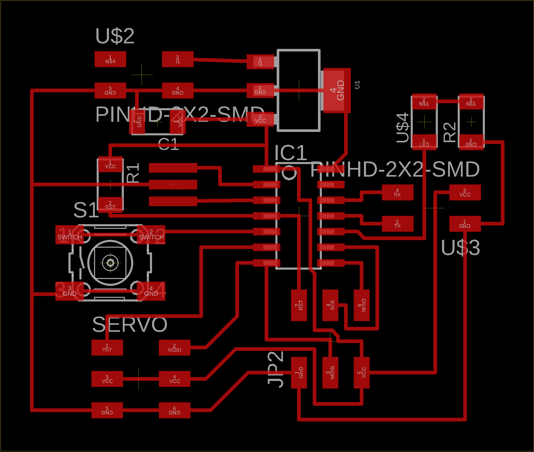
The servo board
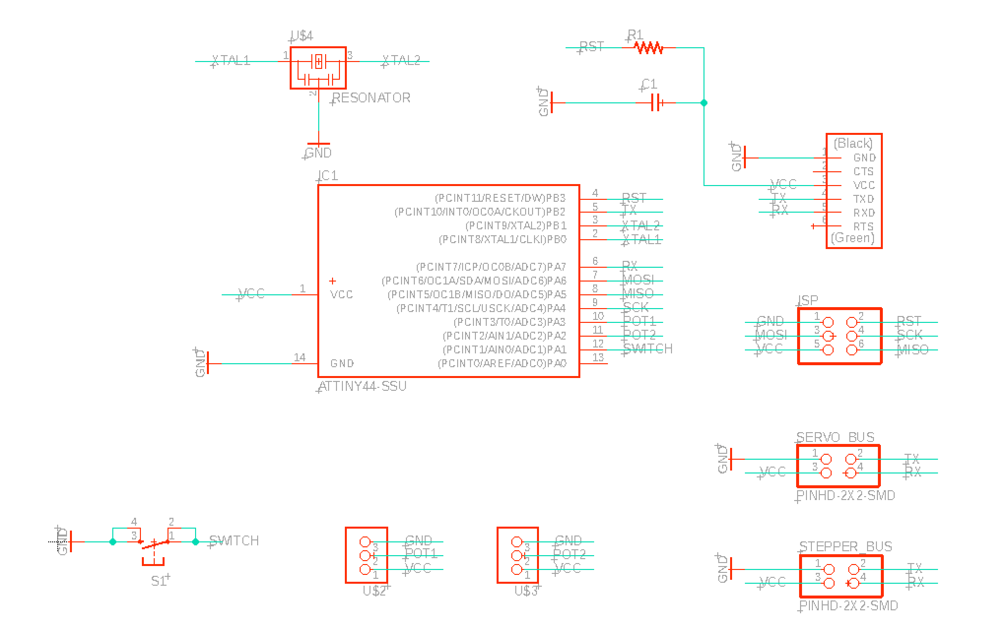
Schematic for the master board
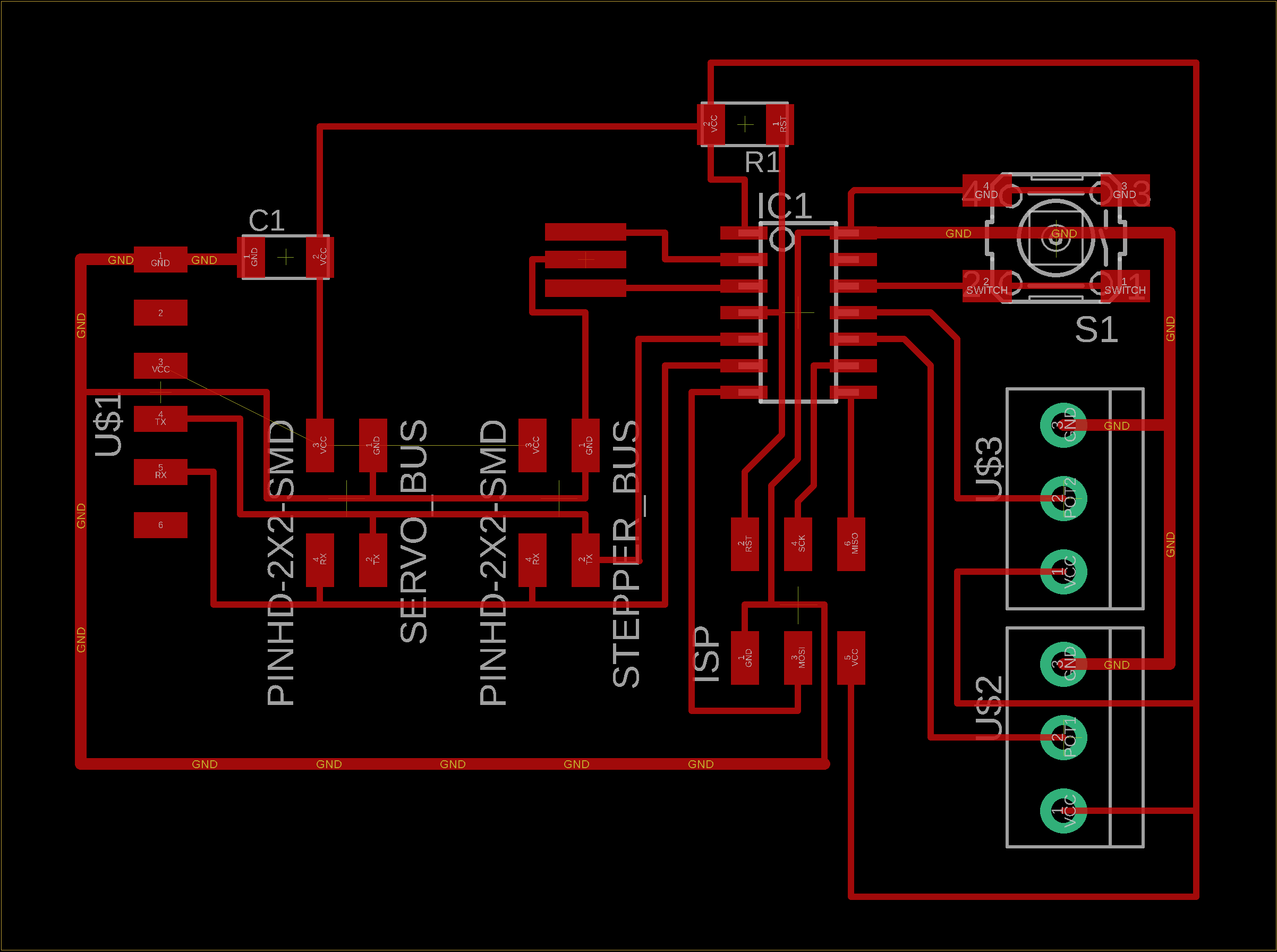
The master board
We both thought about what the master board would need, since this was the board to integrate and communicate with our two independent boards. We added three inputs: the two potentiometers and a button, and two 2x2 headers for communicating with the servo and stepper boards. We also added an FTDI connection so that we could debug all communication / network errors via Serial monitoring, which proved to be extremely helpful.
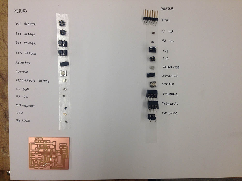
Components for the boards
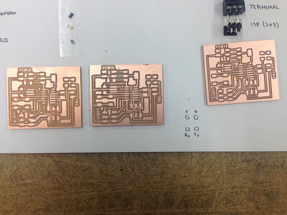
Milling failures due to broken endmills...
At the point when I started soldering, all the endmills seemed broken at the architecture section... I tried all of them after closely inspecting them and not seeing too much difference between them, which resulted in the bad traces above which caused my Bluetooth board never to connect... so I looked further. After 3 hours of trying and readjusting location on the sacrificial board, changing endmills, and changing cut depth, eventually we found a completely new endmill in Jen's office, and I used that to mill a clean board for both servo and master. So many hours later: clean milled boards! Once we found the functional bit, milling and soldering, as well as programming, was very quick.
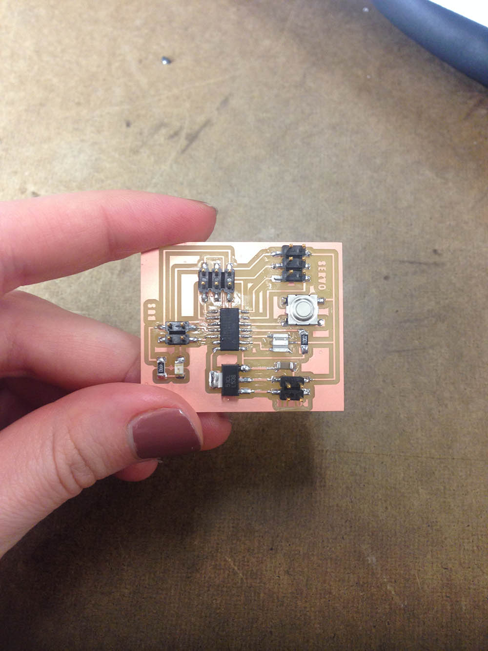
The soldered servo board
The soldered master board
The soldered master board with terminals to connect to the potentiometers.
Programming & networking
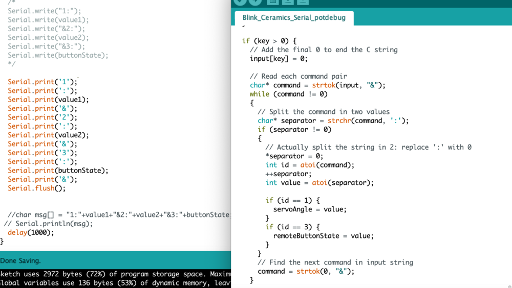
Serial communication and parsing
I used the Arduino & the SoftwareSerial libary to communicate with the boards--parsing the data correctly was particularly difficult (especially without maxing out on memory), but in the end it worked!
Testing sending message from master to servo
/*
 * Dalma Foldesi
 * Ceramic dripper
 *
 * Servo code for opening / closing valve
 *
  Servo PWM:

  https://arduino.stackexchange.com/questions/44760/programming-a-servo-on-an-attiny85

  Parse Serial:

  https://arduino.stackexchange.com/questions/1013/how-do-i-split-an-incoming-string

*/

#include
#include

#define RX    1
#define TX    2
#define INPUT_SIZE 20

SoftwareSerial ServoSerial(RX, TX);
Servo myservo;

const int LED_PIN = 3;
const int SERVO_PIN = 7;
const int BUTTON_PIN = 8;

//int buttonState = -1;
int remoteButtonState = 0;
boolean isOpen = false;
int servoAngle = 0;

// Parameter for receiving Serial command (add 1 for final 0)
char input[INPUT_SIZE + 1];

void setup() {
  pinMode(LED_PIN, OUTPUT);
  pinMode(BUTTON_PIN, INPUT_PULLUP);
  pinMode(SERVO_PIN, OUTPUT);

  ServoSerial.begin(9600);
}

void updateRemoteButton() {
  if (remoteButtonState == 1) {
    digitalWrite(LED_PIN, HIGH);
  }
  // button pressed
  else {
    digitalWrite(LED_PIN, LOW);
  }
}

void toggleRemoteButton() {
  // button pressed
  isOpen = !isOpen;

  if (isOpen) {
     digitalWrite(LED_PIN, HIGH);
     openServo();
  }
  else {
     digitalWrite(LED_PIN, LOW);
     closeServo();
  }
}

void closeServo() {
  for(int i = 0; i< 20; ++i) {
      digitalWrite(SERVO_PIN, HIGH);
      delayMicroseconds(1000);
      digitalWrite(SERVO_PIN, LOW);
      delay(19);
    }
}

void openServo() {
  // keep sending second position for about 400ms
    for(int i = 0; i< 20; ++i) {
      digitalWrite(SERVO_PIN, HIGH);
      delayMicroseconds(2000);
      digitalWrite(SERVO_PIN, LOW);
      delay(19);
    }
}

/*
void updateButton() {
   if (buttonState == LOW) {
     digitalWrite(LED_PIN, HIGH);
     //delay(300);

    // servo PWM
    openServo();
    closeServo();
  }
  else {
    digitalWrite(LED_PIN, LOW);
    delay(50);
  }
}
*/

void readSerial() {
  // We need this counter to simulate Serial.readBytes which SoftwareSerial lacks
  int key = 0;

  // Start receiving command from Serial
  while (ServoSerial.available()) {
    delay(3);  // Delay to allow buffer to fill, code gets unstable on Attiny85 without this for some reason
    // Don't read more characters than defined
    if (key < INPUT_SIZE && ServoSerial.available()) {
      input[key] = ServoSerial.read();
      key += 1;
    }
  }

  if (key > 0) {
    // Add the final 0 to end the C string
    input[key] = 0;

    // Read each command pair
    char* command = strtok(input, "&");
    while (command != 0)
    {
      // Split the command in two values
      char* separator = strchr(command, ':');
      if (separator != 0)
      {
        // Actually split the string in 2: replace ':' with 0
        *separator = 0;
        int id = atoi(command);
        ++separator;
        int value = atoi(separator);

        if (id == 1) {
          if (value != servoAngle) {
            servoAngle = value;
          }
        }
        if (id == 3) {
          if (value == 1 && remoteButtonState == 0) {
            toggleRemoteButton();
          }
          remoteButtonState = value;
          /*
          if (value != remoteButtonState) {
            updateRemoteButton();
            remoteButtonState = value;
          }
          */

        }
      }
      // Find the next command in input string
      command = strtok(0, "&");
    }
  }
}

void loop() {
  readSerial();

  /*
  buttonState = digitalRead(BUTTON_PIN);
  updateButton();
  */

  delay(300);
}
Testing networking (with stepper and LEDs in off state)
Testing networking with both servo and stepper
Valves
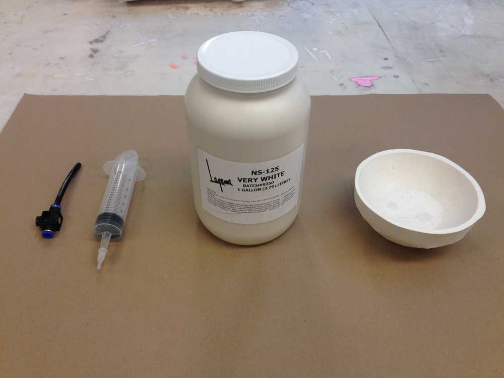
Choosing the slip dripping mechanism
I tested both our solution for the machine week drink dispenser and a syringe for 'extruding' liquid clay, and it seemed like while I could drip using the valve, the syringe only led to an uneven combination of flow and drip. I decided to refine our previous, purchased valve and 3D print our own instead.
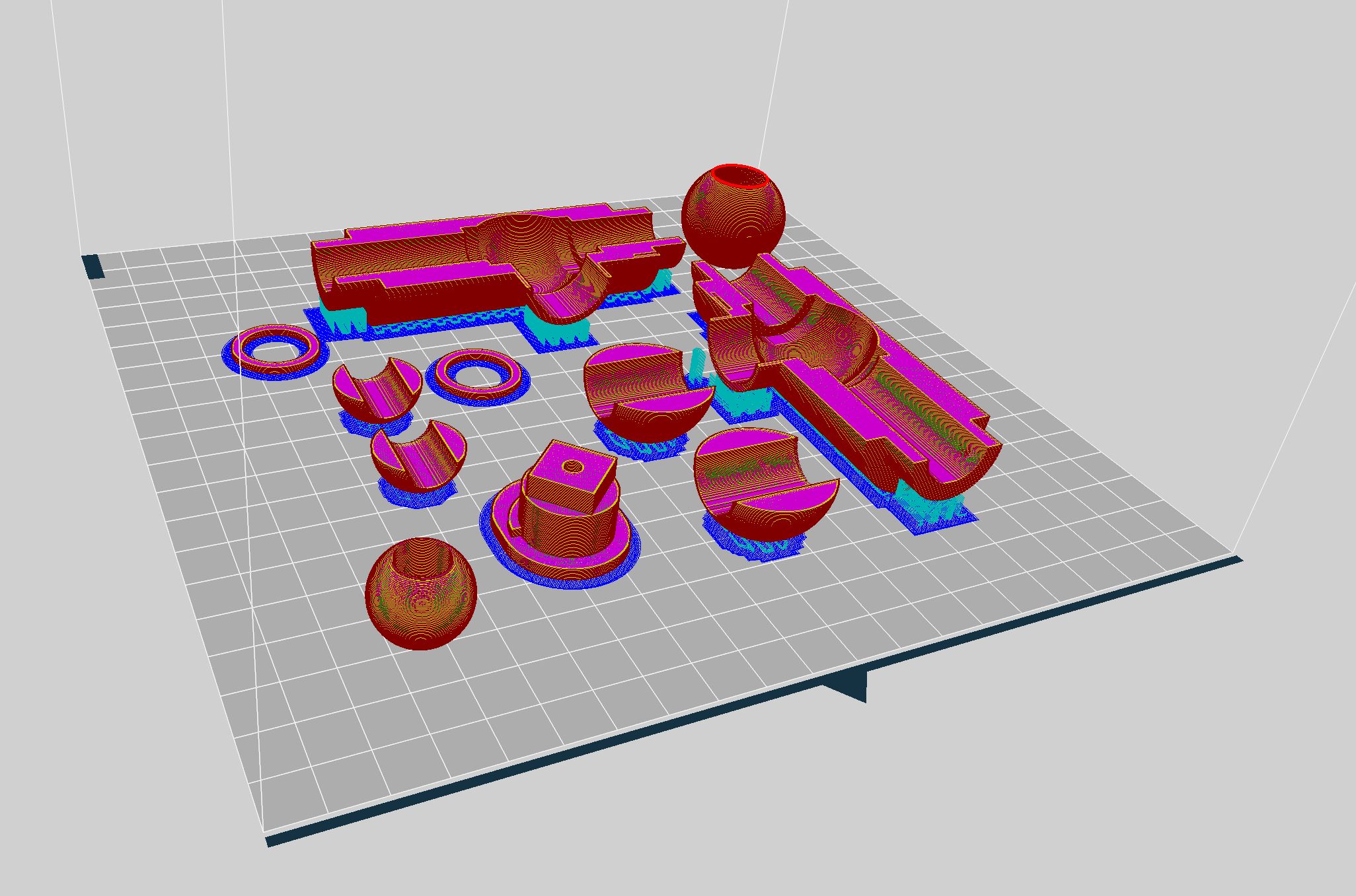
3D print setup
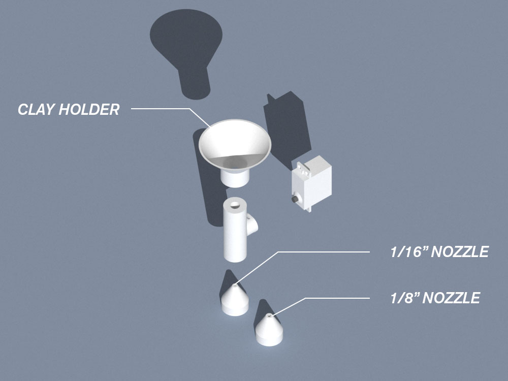
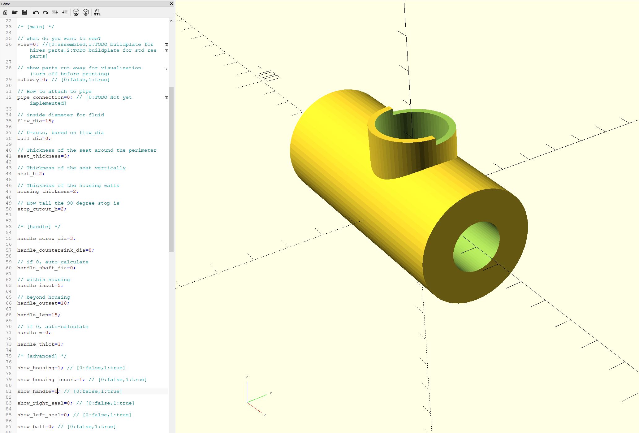
I wanted to test 3D printing the valves with different cross-sections, and I found an OpenScad design for one on Thingiverse here which I ended up customizing using the OpenScad interface to set up multiple prints. I also designed different nozzles (with different outflow radii) for this & a connection to a supported bottle to receive the clay.
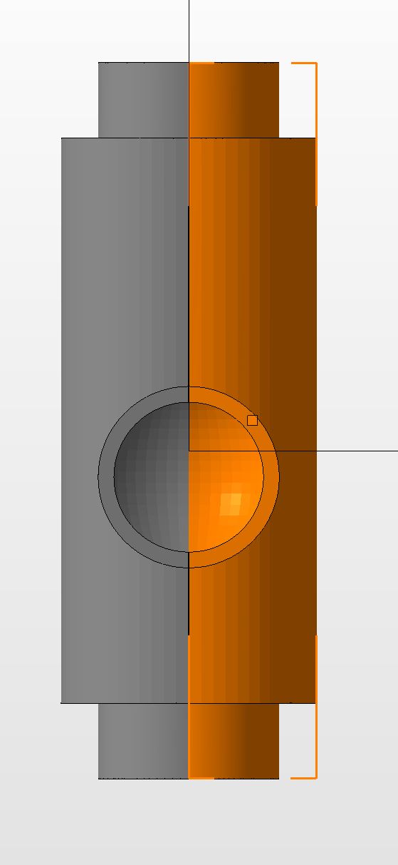
OpenScad modifications
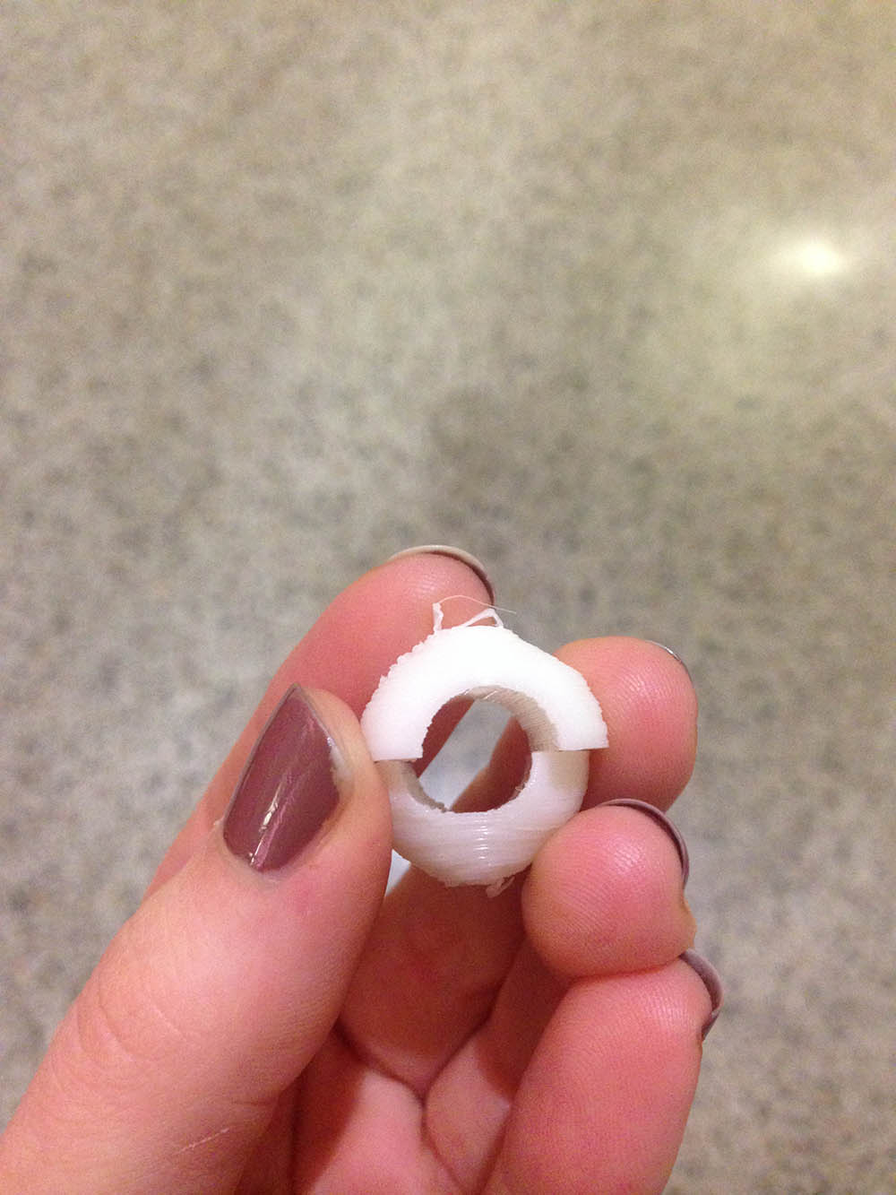
I had to manually split the output mesh in two halves using Netfabb to be able to print & assemble the valve.
Netfabb splitting
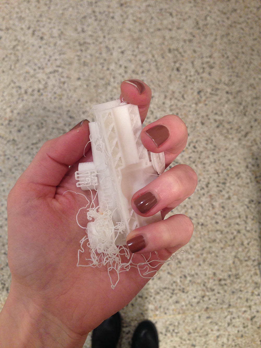
Many many failed Sindoh prints
Final success after many failed Sindoh prints
Final success after many failed Sindoh prints
There was only one roll of filament left at the architecture section by Sunday, so I had to use that for printing all my valves and nozzles--after many many failed filament insertions by the machine and fixed beds, the prints finally came out.
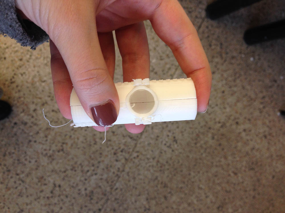
Waterproofing the valve
I then had to coat the valve in lots of Tamiya white plastic putty--and even after quite a few coats, the valve wasn't completely waterproof, but sealed enough to hold liquid clay.
Nozzles and connection to bottle
The print of the bottle joint and the nozzles was successful, and the fitting was also tight enough to make a good connection after sanding.
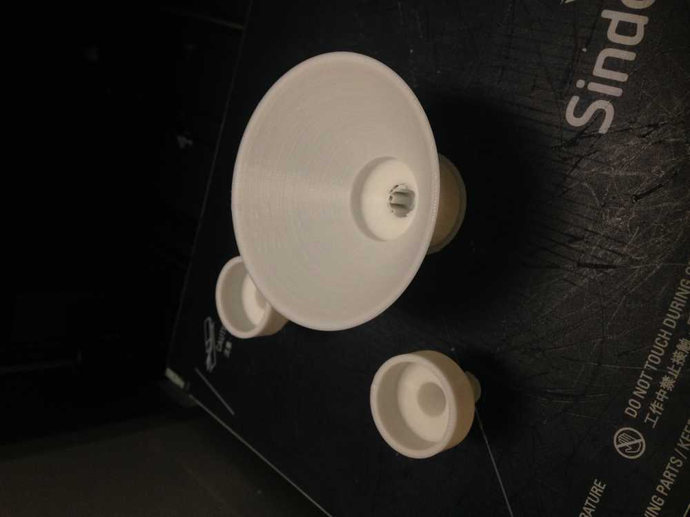
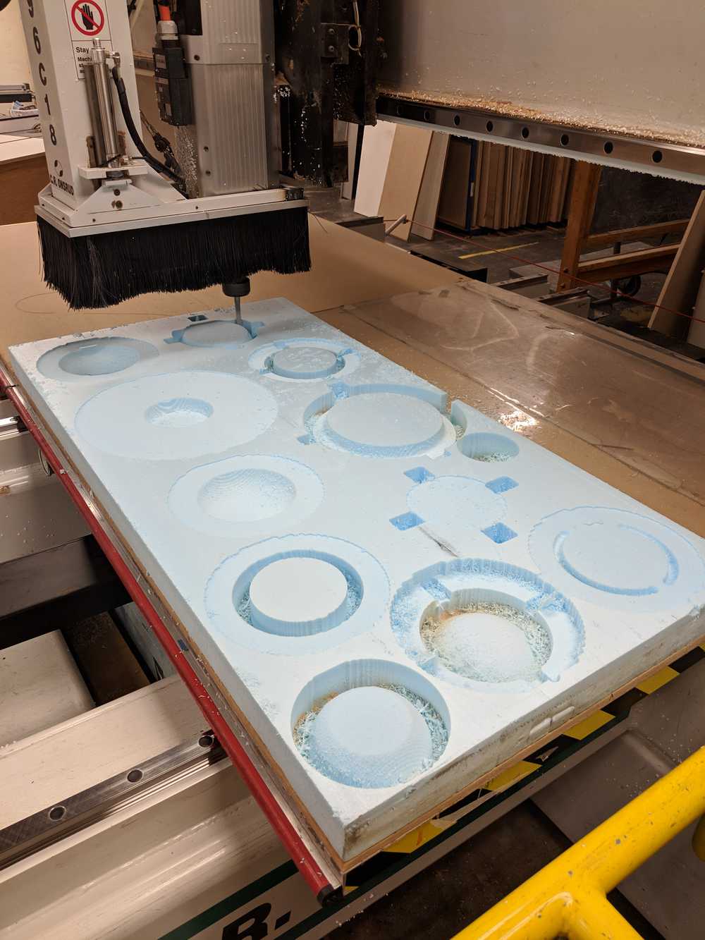
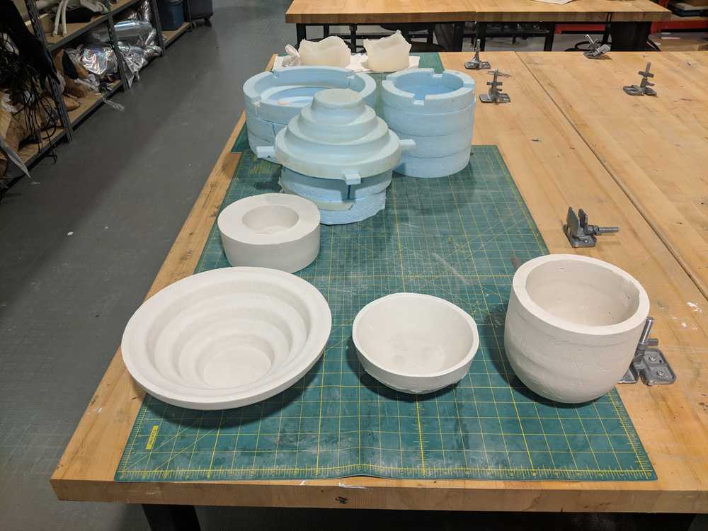
Plaster forms
Plaster formwork
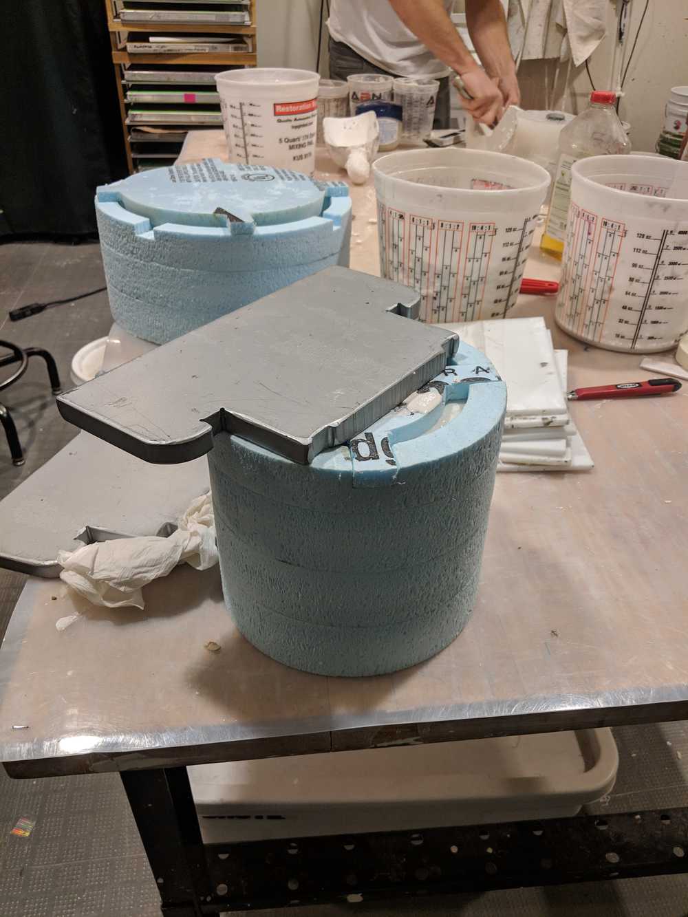
I created the 3D formwork for the plaster casts in Rhino, which we then milled on the Onsrud and glued with 3M Super 77 to keep it securely sealed. We each cast into one or two the foam formworks at the Mars Lab (ACT shop) with Graham's supervision, who also introduced us to the 'island method' of casting plaster, where you first create a small heap of plaster, then let it sit for a minute or so, and only after that you mix.
Milling
Casting
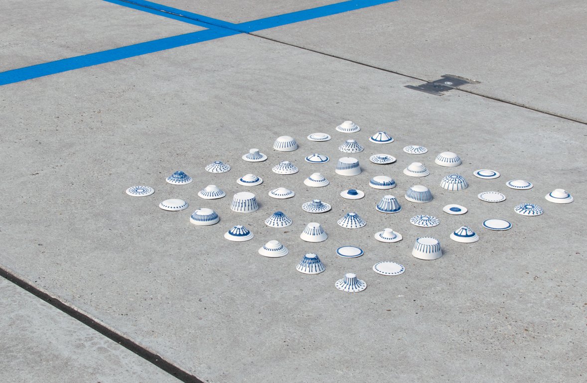
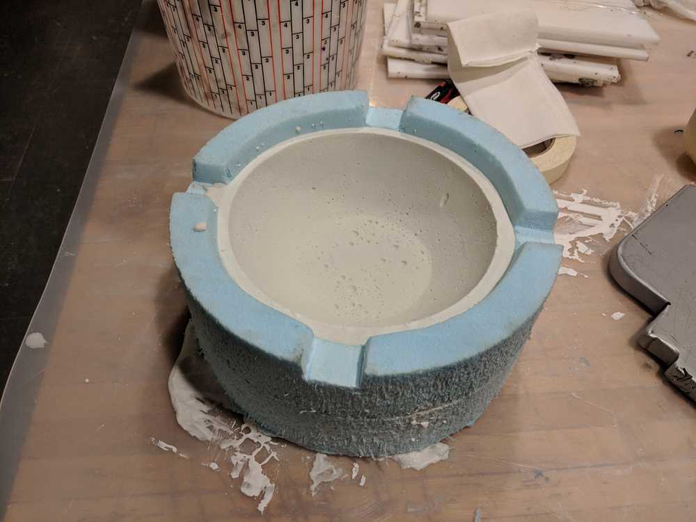
Demolding
Demolded forms
We then left the formwork to dry for about 3 days, after which the bowls didn't feel cold anymore.
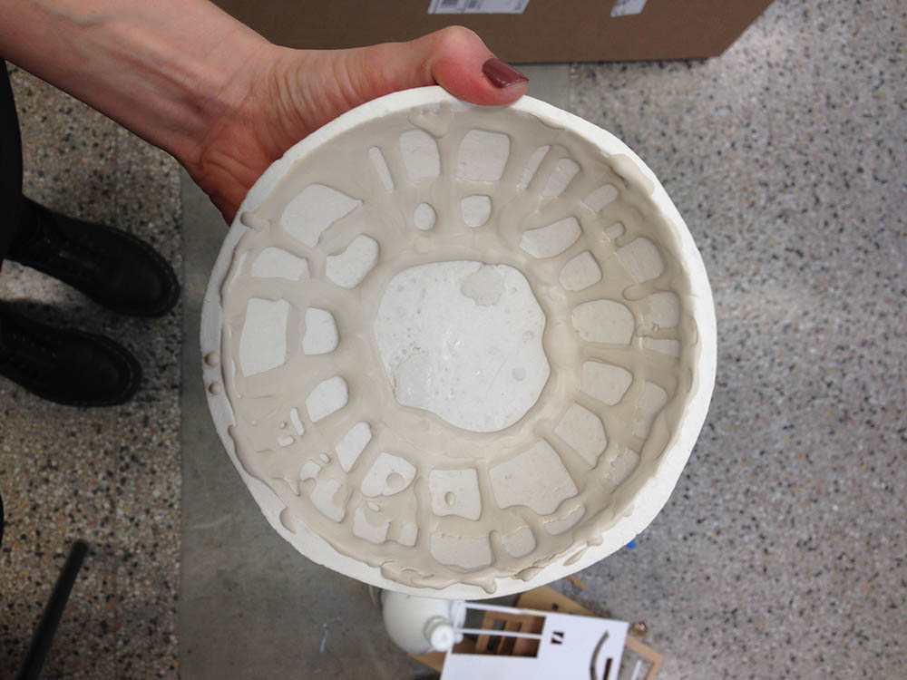
Slip test: too early
I tested a syringe and a valve for dripping slip onto one of the bowls before it completely dried, and while it helped me decide on the valve (the syringe wouldn't allow dripping at a constant rate), it didn't demold because the plaster was too wet.
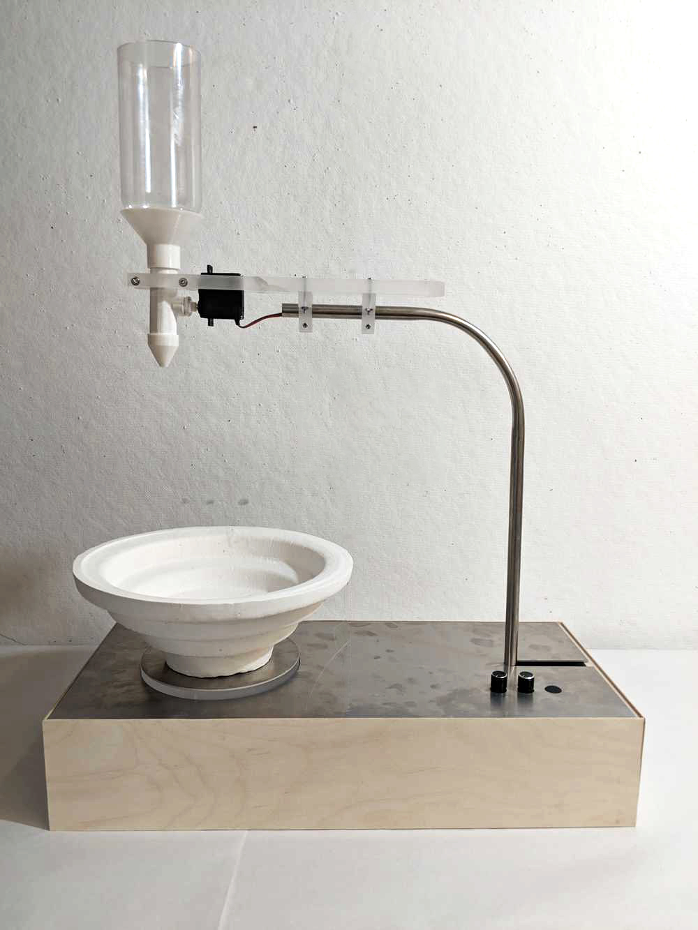
Assembly!
Assembled machine
I bent our steel section at the Mars Lab while Jung waterjet and cut out the parts for the lower half of the machine. We inserted the servo, stepper, potentiometers, and jumped the button to reach the interface.
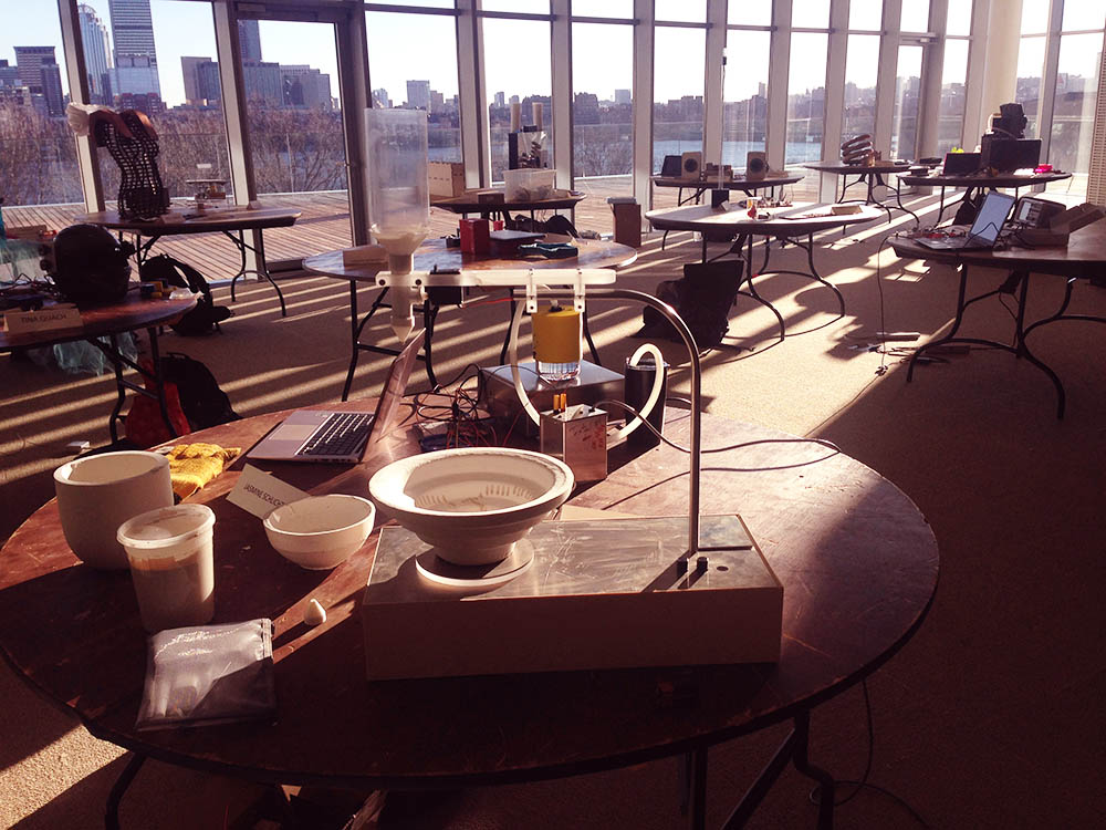
Testing the servo's connection to the valve & calibrating its rotation
Dripping!
The communication and the hardware all seemed to work fine, except that the button was *WAY* too small and jumping it caused some unforeseen errors. In retrospect, we should have ordered a new button earlier... it is the first item on our to-do list. In addition, there was some power leak from the Stepper board to the other two, since all the boards shared ground. But overall--the machine was moving the valve, rotating the platform, and dripping clay!