Computer-controlled machining

1 2 3 4 5 6 7 8 9 10 11 12 13 14

Designing the impossible

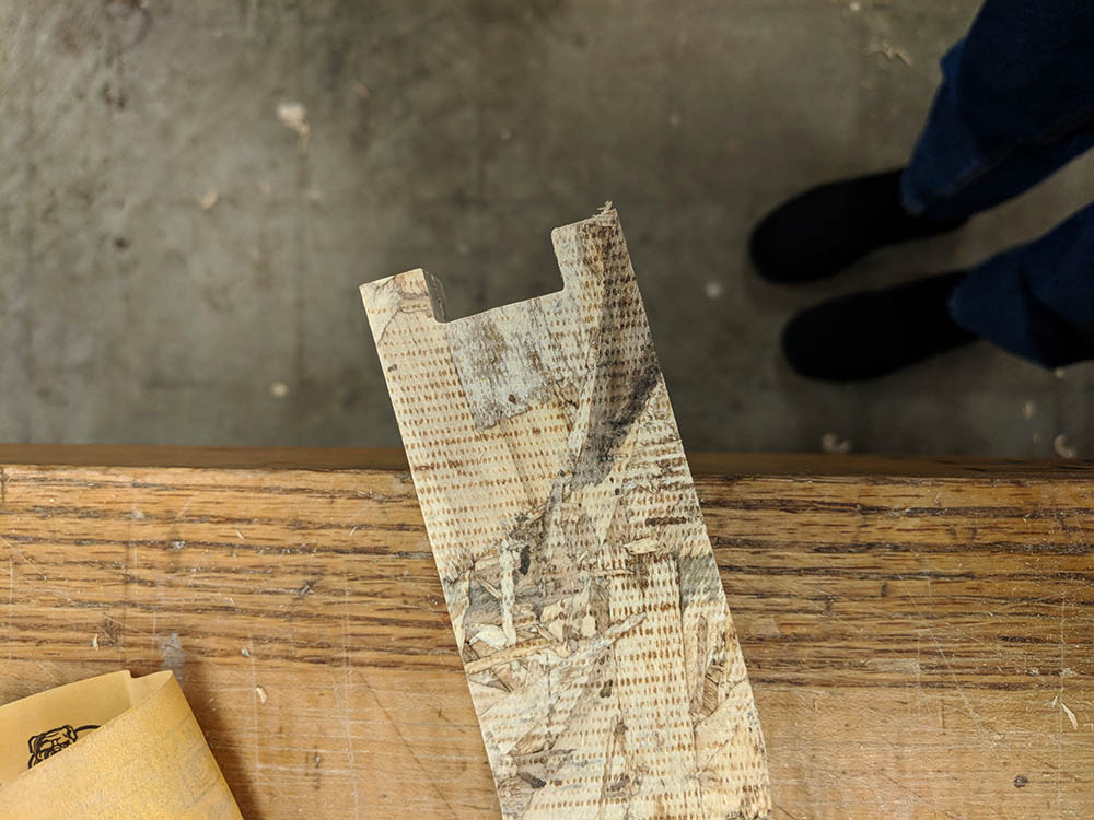
Leg design iterations
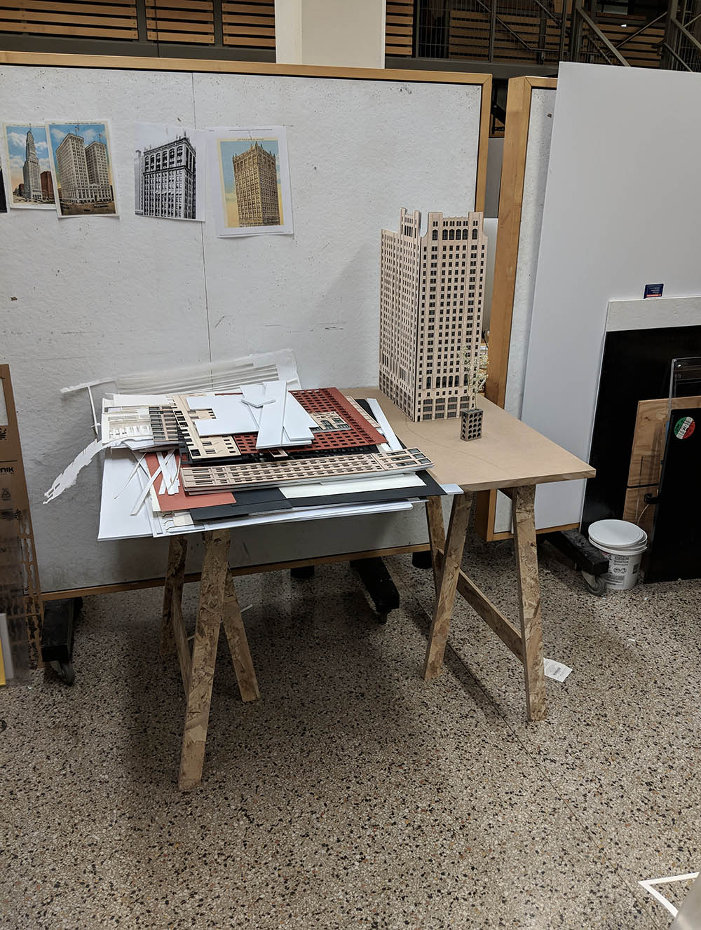
Final table

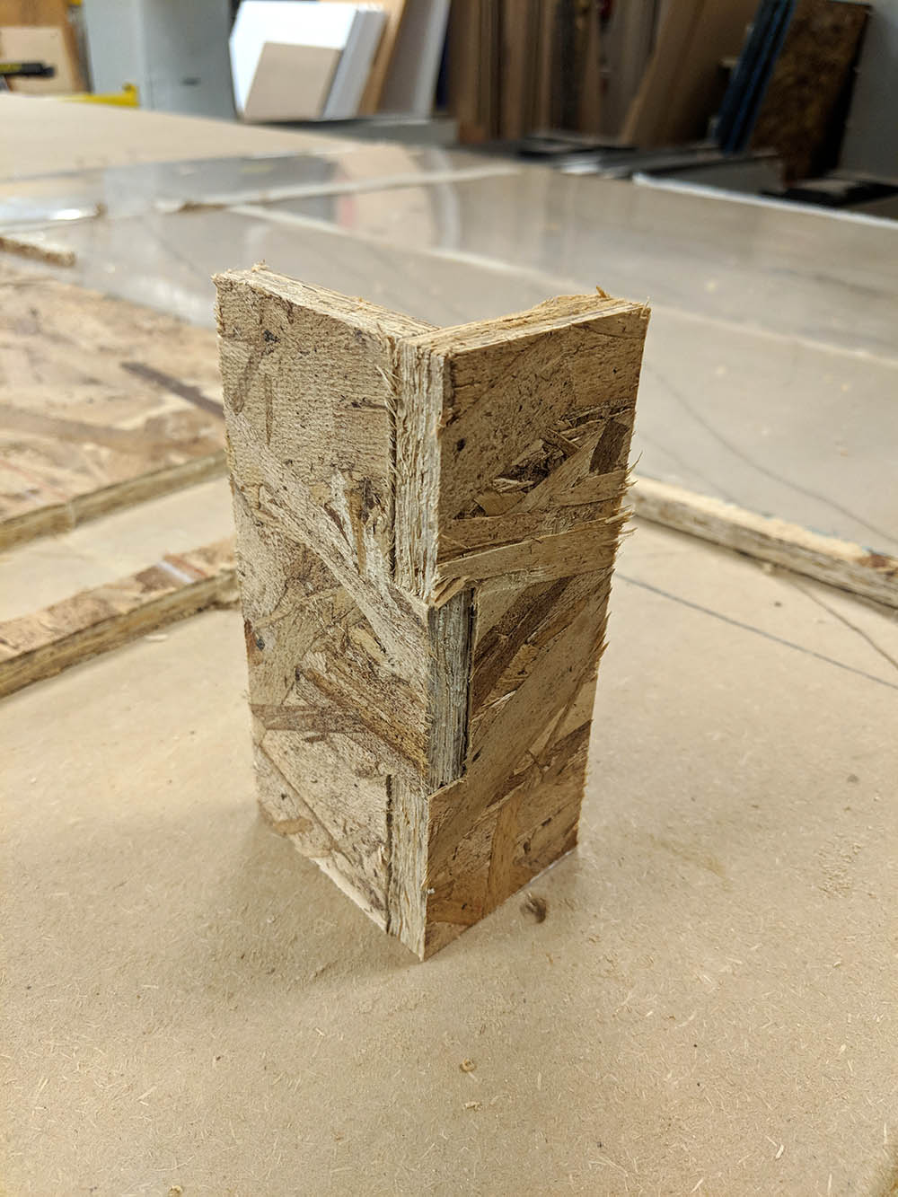
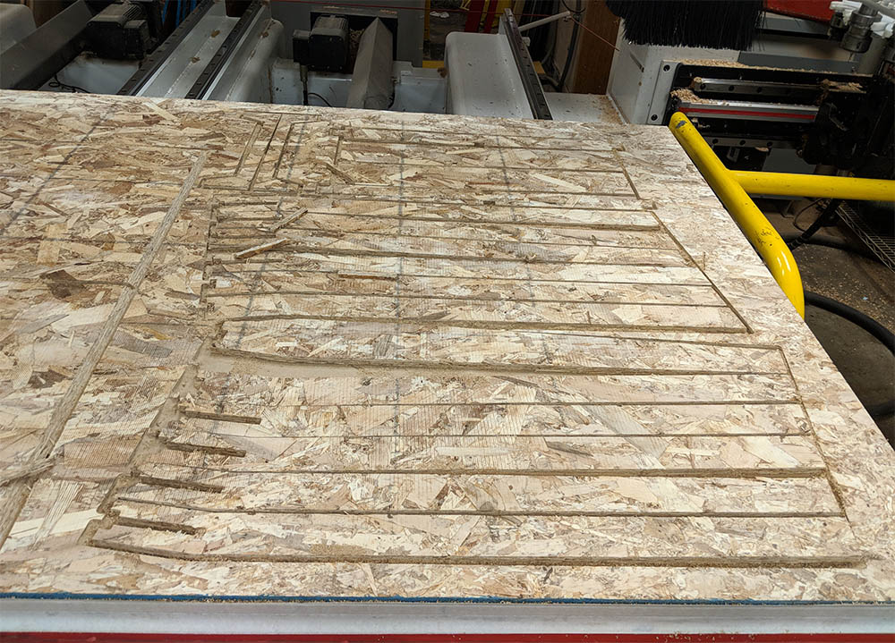
I am in the process of building a large (1:150) site model for my studio project in Chicago. We were only provided with MDF for the base (1/2" thick), and we had to buy / make our own legs. I thought I could maybe prototype possible legs for model stands that I could reuse in the future, and initially I also wanted to be able to easily disassemble, store, and reassemble them. (Site models every semester!)

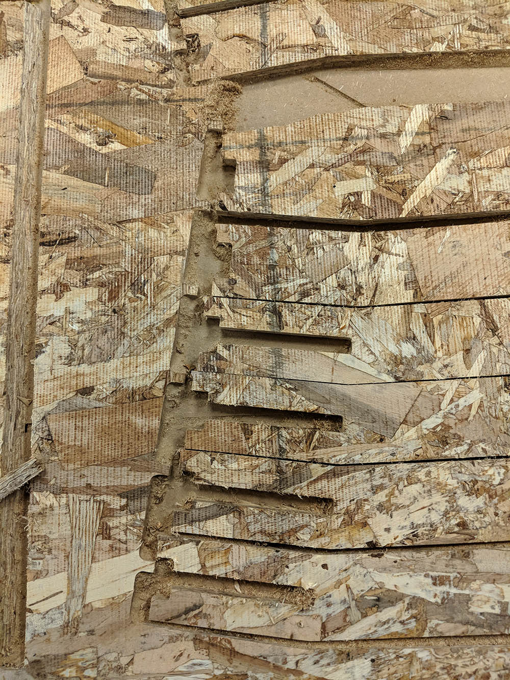
I quickly realized that this was seriously wishful thinking. The structural properties of OSB are... not quite appropriate for a table. According to Chris Dewart, "the material has not much more structure than a cookie." The thing I had in mind, something like this Hay structure, was definitely not something OSB is good for, so I had to make many adjustments to my initial design. Big thanks to Jung for tips on how to make this work!!
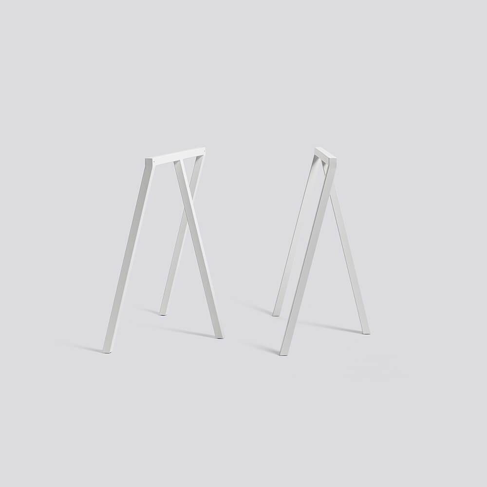
Precedent from Hay
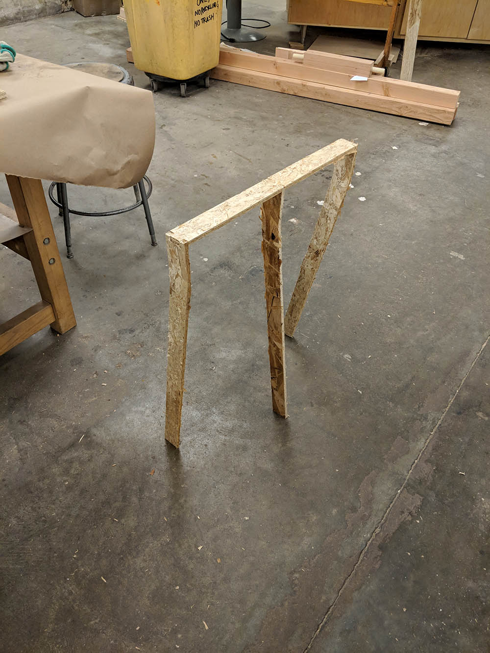
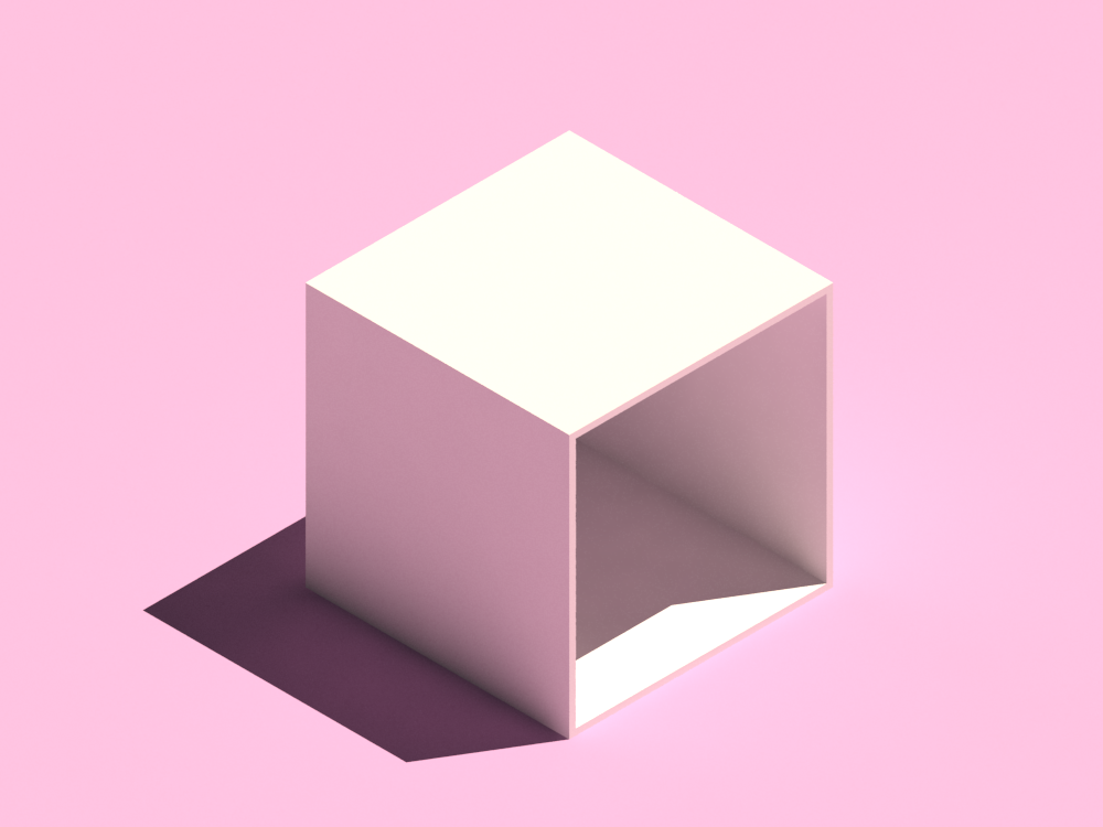
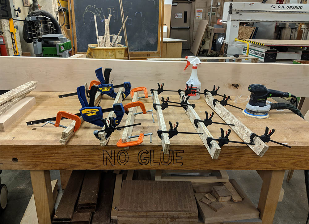
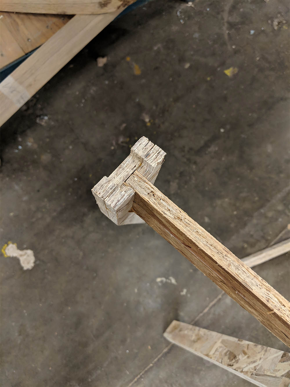
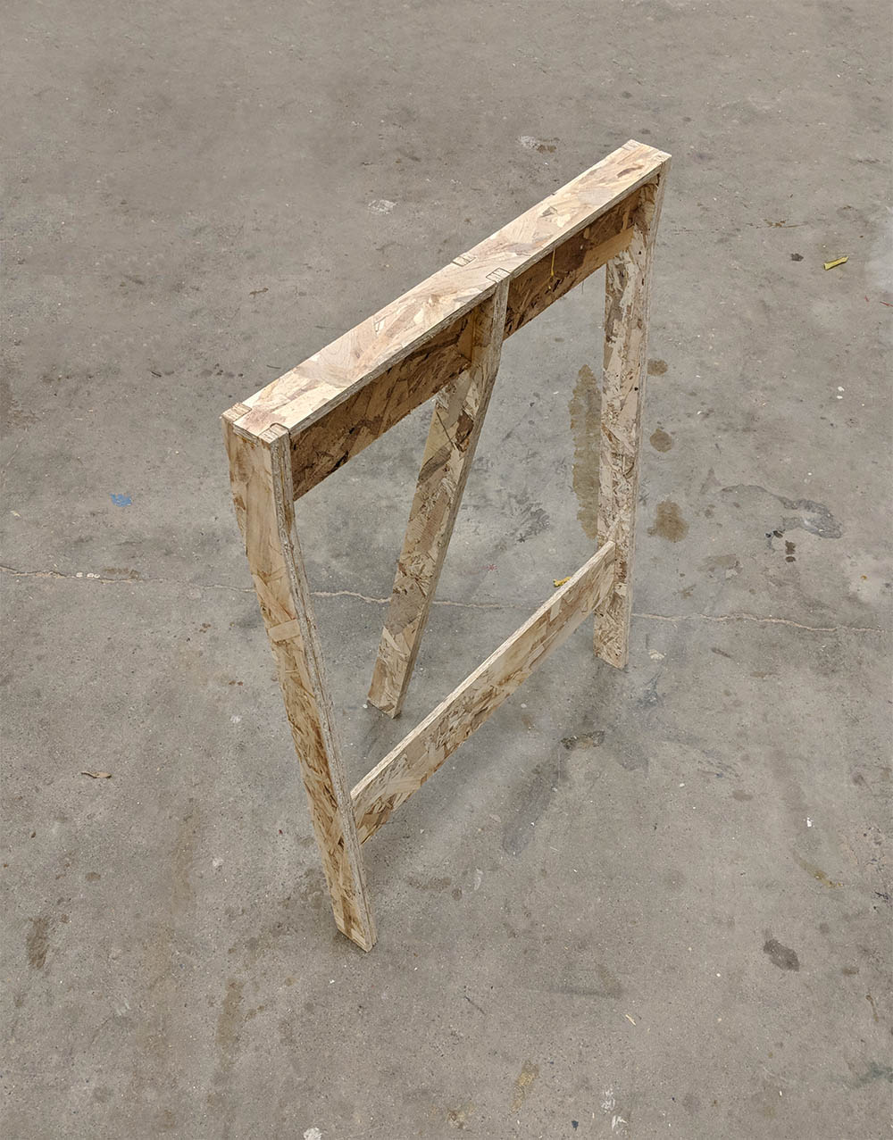
Testing the extremely flimsy leg assembly (& what was I thinking?)

I had to reinforce the simple & beautiful, but not-quite-suitable-for-wood design to make it stand & hold the weight of the MDF & that of my model.

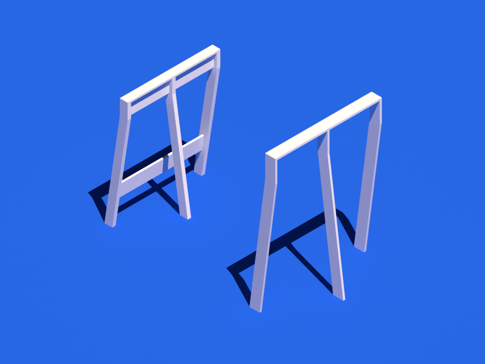
Final vs initial leg design
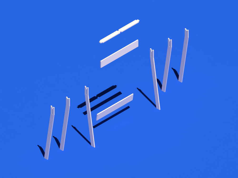
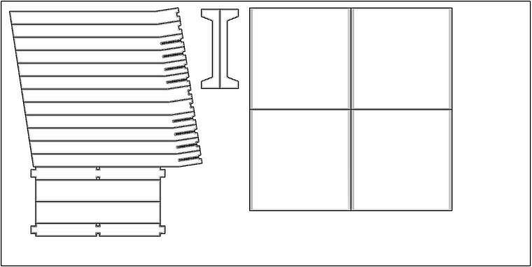
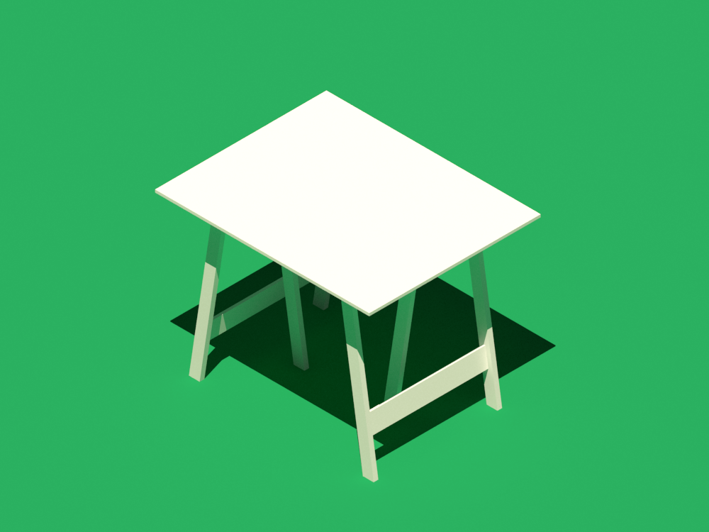
Exploded view of the final design

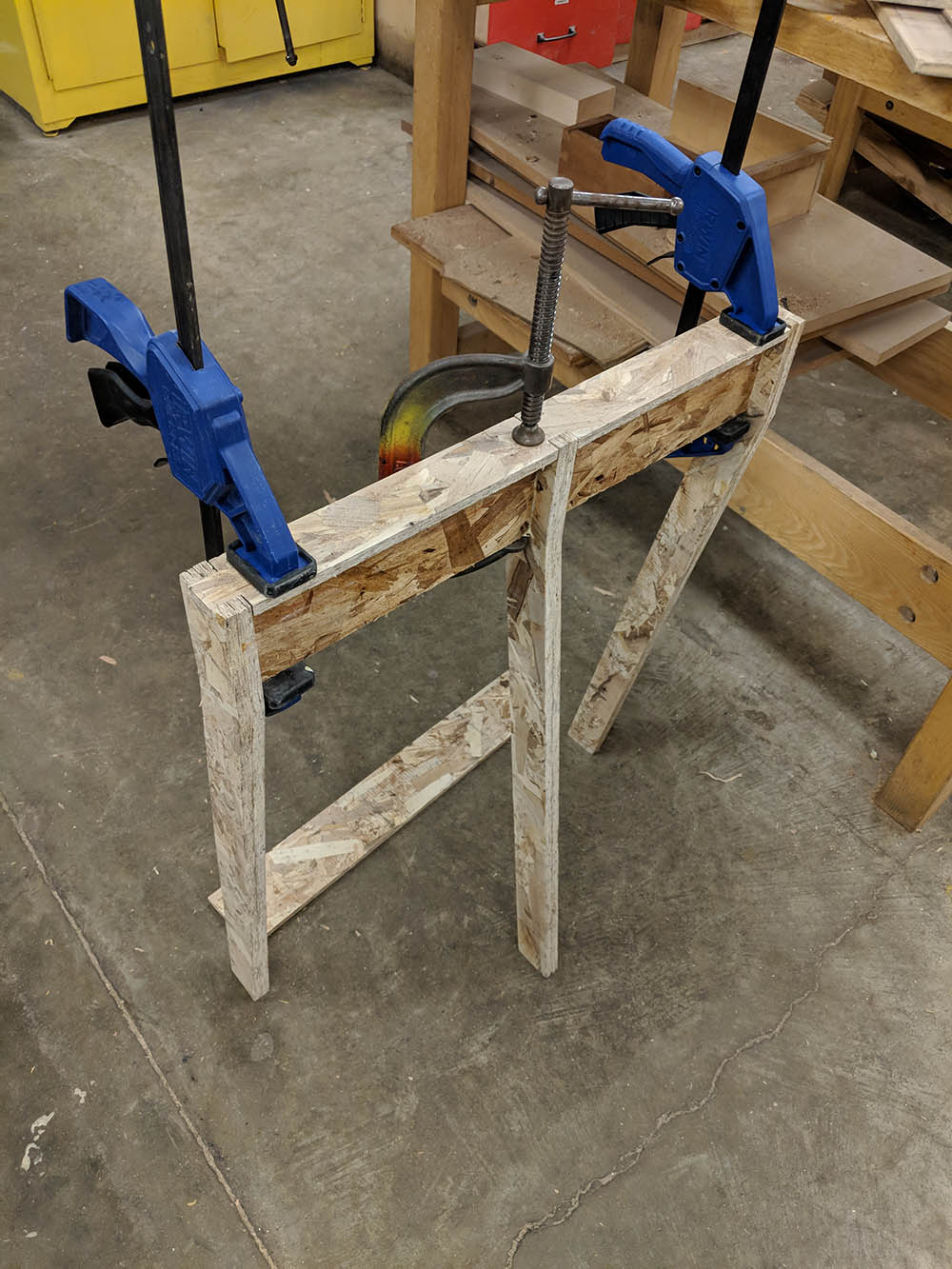
I doubled up the two sides, and I added an additional beam running across the two sides to the full depth of the straight section of the legs. Following Jung's advice, I also added a cross-beam on the bottom to better fix the rotation of the leg.

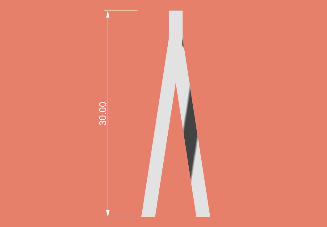
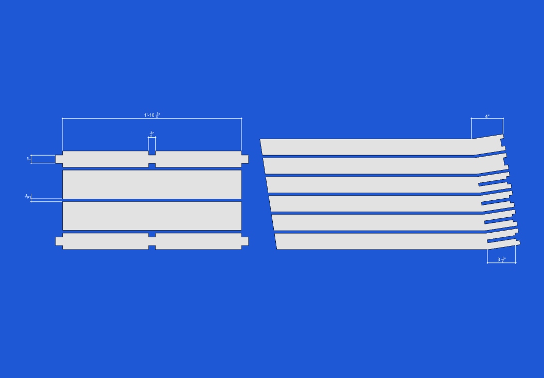
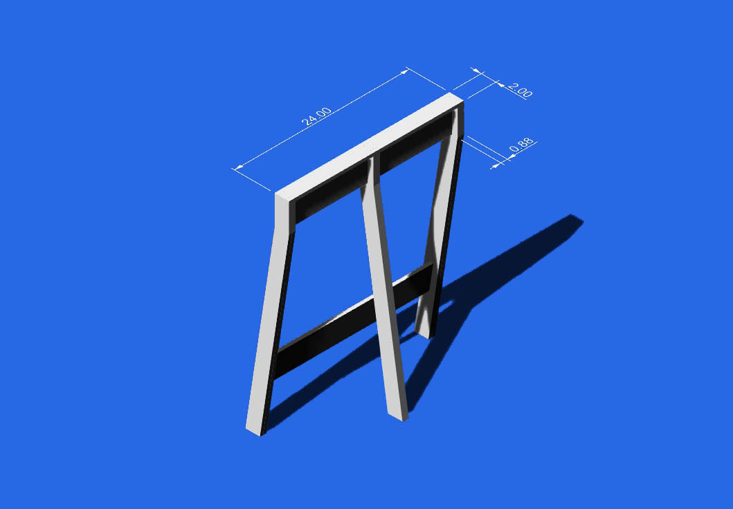
Dimensions of the final design

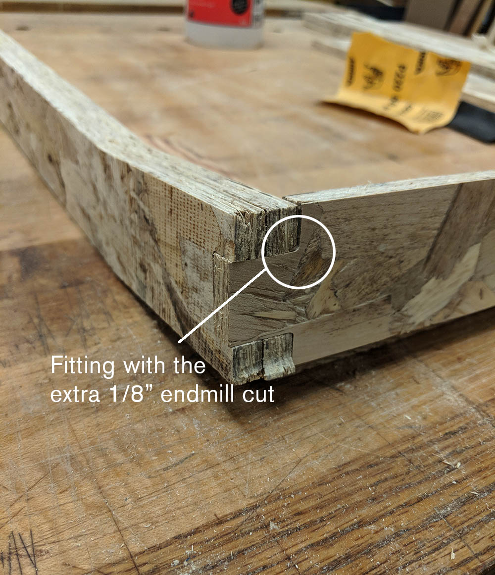
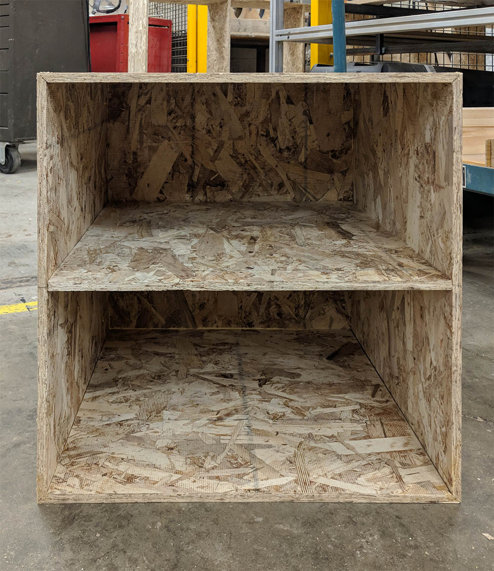
I also added a small mitered box to the sheet to not waste material, since I already had a 32"x40" sheet of MDF for my site model that we cut down on the tablesaw.

Small box

Milling & assembly

Press-fit testing

Jung and I tested multiple cutting methods and the fitting of two sheets, as well as their thickness. I also wanted to test cutting out the leg profiles with as little spacing and as few cuts as possible, so in my final layout, I used a 3/8" offset for all the pieces with a single curve for the toolpath between the elements that stacked perfectly.

Layout on the 4'x8' OSB

I already had the table's top, so I also added the small box & ended up using the leftover space for all the corrections / recuts we had to make later (for better fits/ for correct dimensions).

Layout
Milling issues
Milling issues

The single cut was very fast, but as soon as the pieces were mostly cut out, some of them started moving & the final cut messed up one piece entirely, since it had moved considerably. I already had a backup piece, though, so I could use that instead. We could have left a tiny bit of stock on the ground to keep the pieces attached so that they don't move, or used small tabs to connect them to the stock.

Sanding
Post-glue clamping for the doubled-up legs
Fitting test
The 1/8" corner fillet

In order the fit the pieces without making little circular cuts at the corners, Jung recommeded adding an extra path at each corner with a 1/8" tool, which improved the fits & made almost-perfect connections.

Fitting test

At first, the middle spanning piece was too loose, and this took away from the structural properties significanly--the legs were too wobbly. We had to cut another piece on the tablesaw to make a good & tight fit to secure the connection between the two sides.

Gluing the cross beam
Standing & stable!
Standing in studio

The little box I wanted to make with the extra material caused so many headaches... I definitely should have spent more time on its design.

Box assembly
Box assembly

We ended up having to add a back sheet & another sheet to divide the interior in two. Without the backing, the box was way too large & weak.