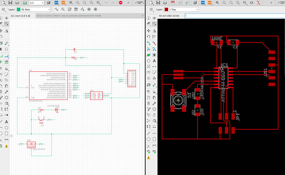
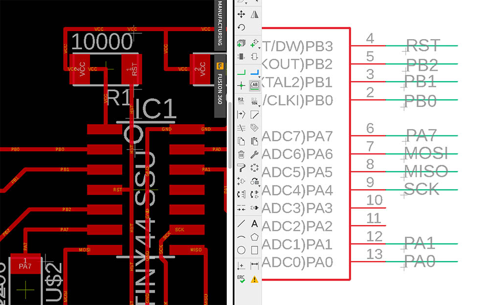
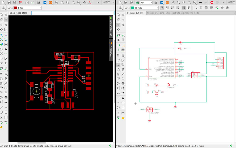
Electronics design

1 2 3 4 5 6 7 8 9 10 11 12 13 14

Eagle

Eagle
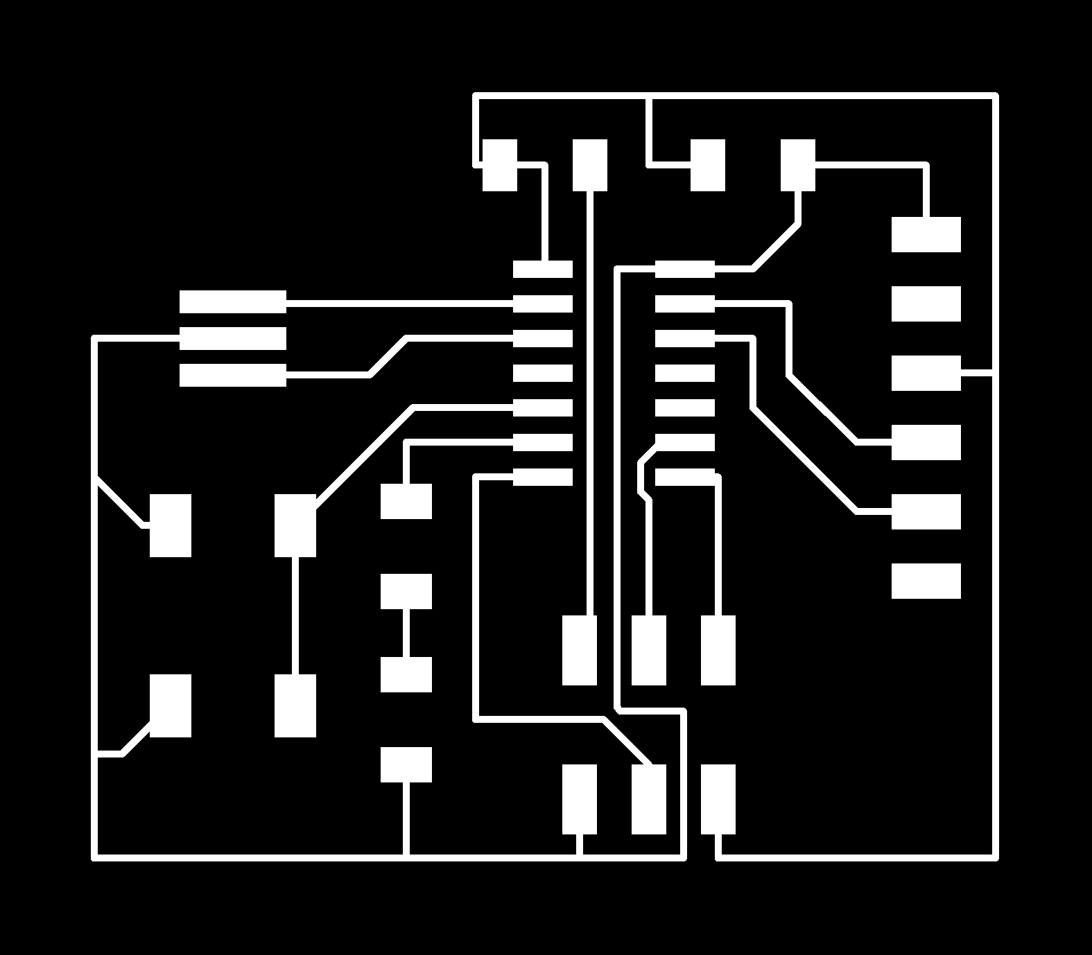
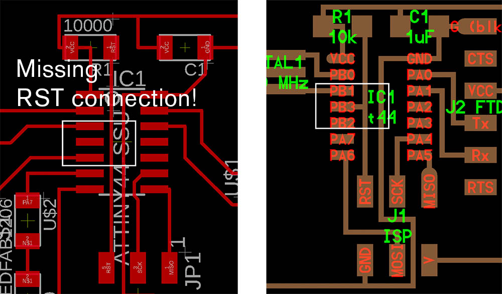
Ground connections cleaned up (some connections missing)

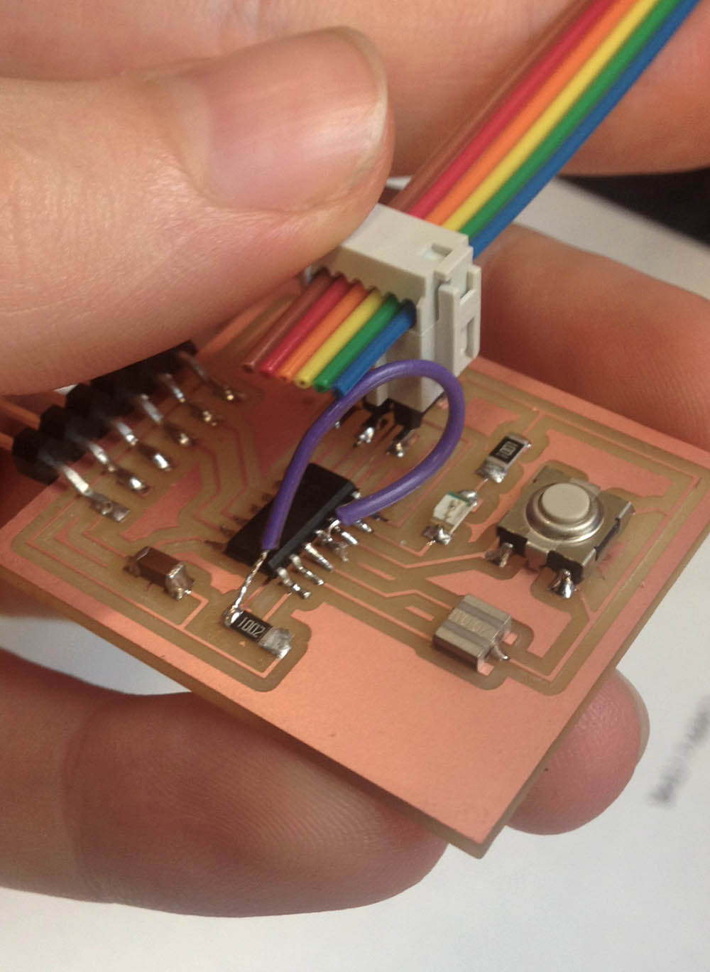
Our task was to reproduce the board here and to add a couple of extra components to it, then program it. Unfortunately, I missed the Eagle tutorial in recitation due to an architecture studio review (always on Thursdays unfortunately!), and I'm really grateful to Axel & Paloma for catching me up on Friday! Still, there are definitely gaps in my understanding, and I spent quite a bit of time getting used to the interface. I found NAME-ing parts extremely useful, and I only learned about the design rules & the fab library on Friday, which otherwise made it impossible to copy the components.

Initial board

My initial board was (still is!) probably too large and strangely distributed, but I tried to follow the traces on the website to create a more compact design. I had to move parts together several times to get a smaller area, plus I also had the Mac 2x resolution issue, where my board turned out to be 4" x 4".

More compact, smaller board.
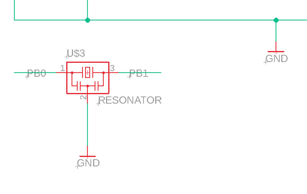
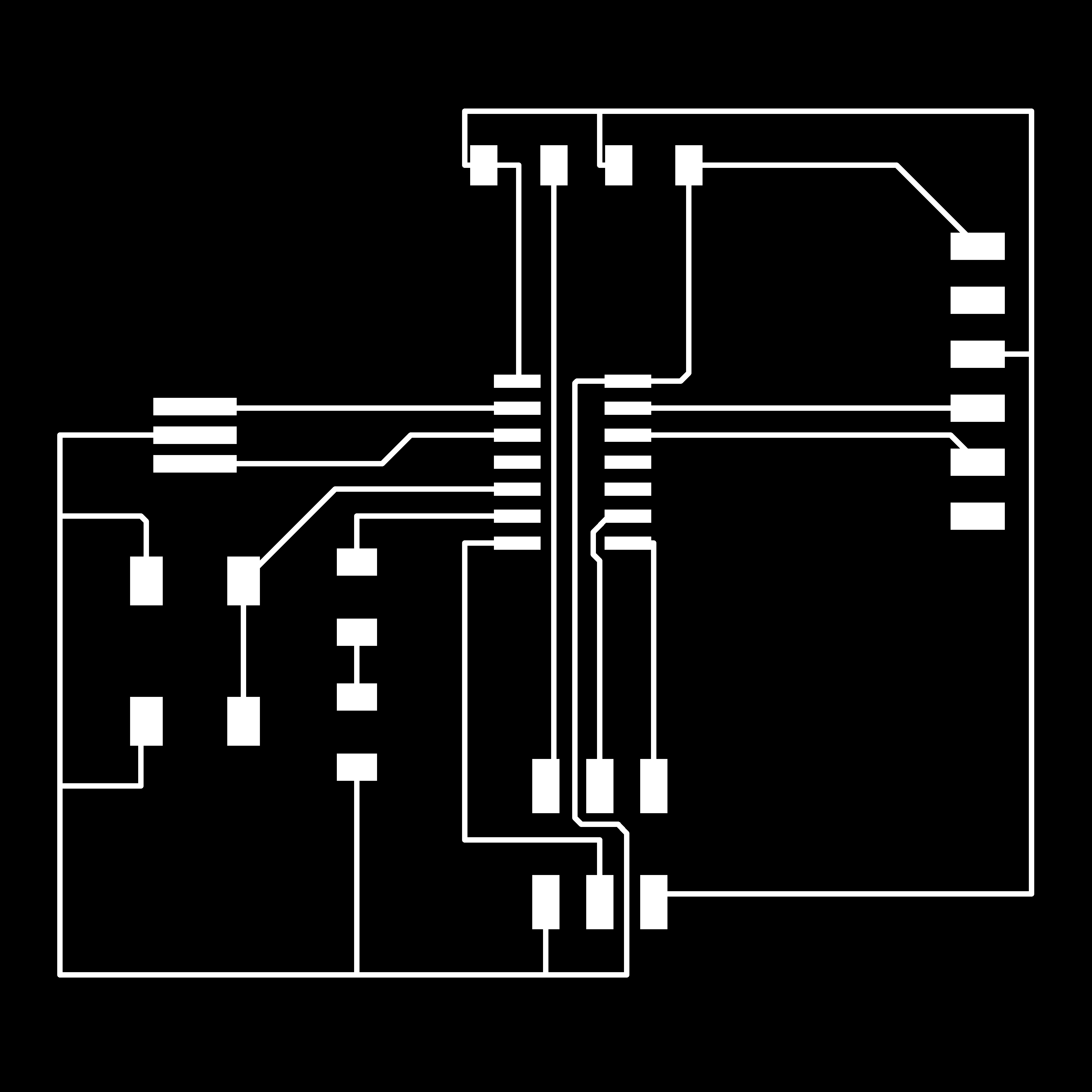
Which way is better to connect to GND? Multiple small ground connections seemed like the cleaner option.

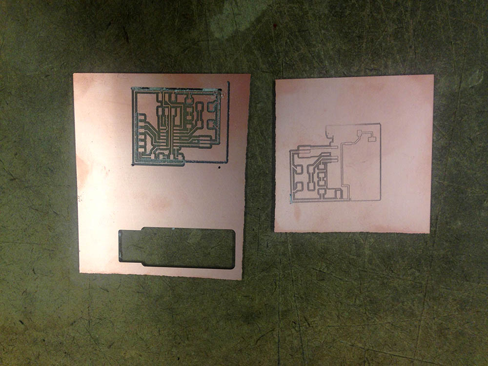
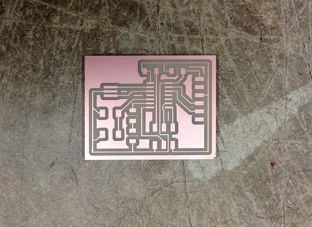
Finally, all the connections were good and the board passed the design rule check, so I moved on to milling.

Milling & soldering

Many milling issues

Milling was very straightforward last time, and I was hoping it would be quick and easy again. But it wasn't. The copper sheet kept being uneven and my traces would not cut through consistently (probably due to a combination of my double taping, the surface below, and the toolbit may also have been broken). I had to try at least 3 times until I could mill the traces, and the initial boundary I used for the 1/32 cut was also too thin and didn't cut first.

Finally, both my traces and outline worked & I got a nice mill.
Components to solder

Soldering was much faster than last time, and this time I made sure to use the magnifying lenses as well.

Programming

Programming setup

I ran into several issues while trying to program the board, and I finally realized, ~~~big thanks to Rafa~~~ that the main issue was that I completely overlooked a reset connection in my Eagle board / schematic setup! But before we get there, the following were the intermediate errors I noted:

VM error

I couldn't, very likely due to my incorrect wiring, get the board to connect using the VM, so I moved to Arduino following the steps described here to see if I could do any better.

Arduino error

After fixing a USBtinyISP connection error (not sure how, but after connecting and disconnecting a couple of times, it just worked), my board would still not transmit the message from the programmer. My Arduino setup seemed correct, and we managed to get the same setup to work for Rafa's board, so I became suspicious that there was actually an issue with my PCB wiring. We debugged each connection, and as we got the the Attiny44, I suddenly realized that I may have made a mistake while renaming the connections. Initially, I connected all the reset buttons with a RST NAME, but I then changed the name and lost one of the connections--and completely forgot about it! So my RST pin from the Attiny44 did not actually connect to anything!

The big mistake
Fixing the big mistake...

To fix this issue, I had to add a jumper, and Rafa showed me how to do this. After soldering the wire, I reconnected the programmer and the Blick / Button Arduino scripts worked! My LED was pin 7, and the button pin 8. I'm not sure if the button was well-wired, as it was a little inconsistent, and I know I could have added another resistor there.

Fixing the big mistake (board & schematic)
Blinking LED & button test