PCB design
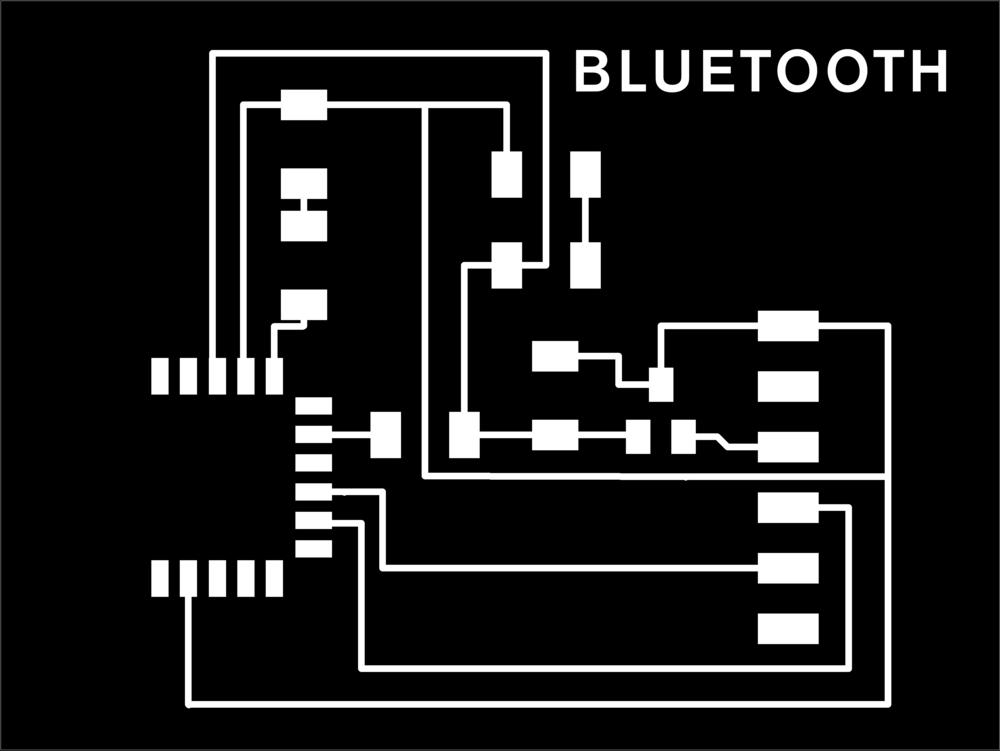
Bluetooth traces
Since it's our studio final review week and I have been CNC-ing for days, I decided to set more reachable objectives for this week and followed Rodrigo's tips here and retraced Neil's wires for using a RN4871 2.4 GHz Bluetooth module, adding LED's as per Rob Hart's advice to the board to help debugging.
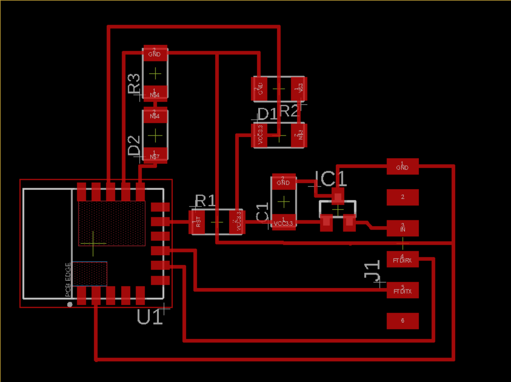
Wire width issue in Eagle; had to set with to 10 again in order for the Design rules check to pass
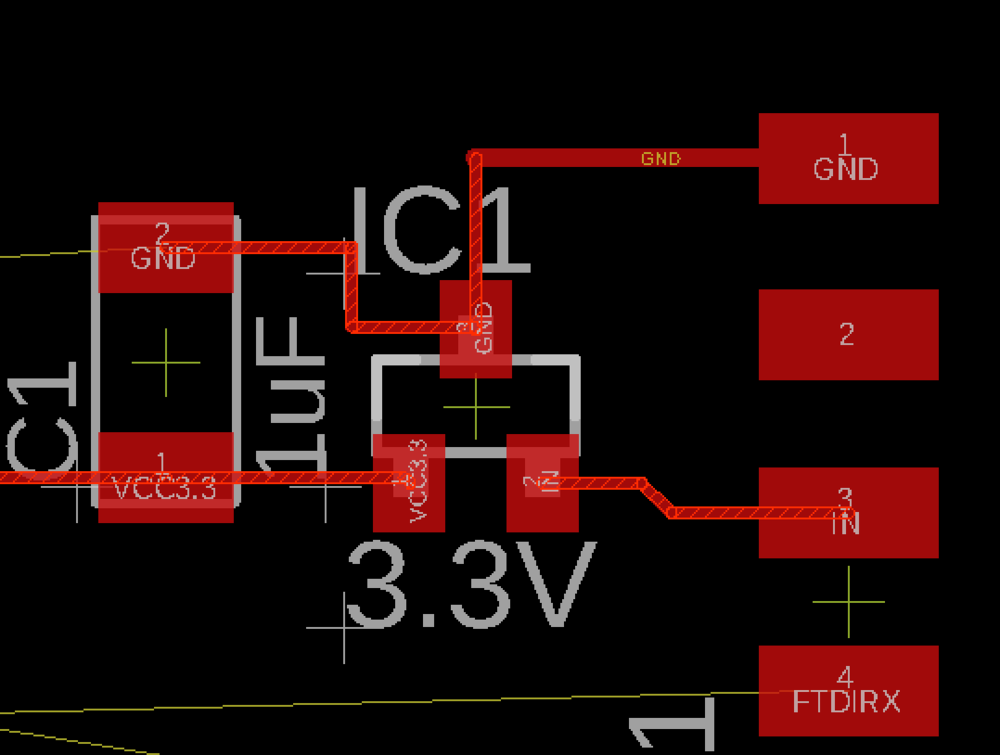
Wiring issues: how to connect VCC
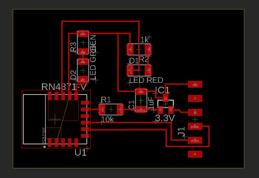
Final wiring
As last time, I had some wire width issues in Eagle and I also made the traces further apart (image above) to avoid the milling tolerance error I had last time, that had caused the board to be disfunctional until cut by hand.
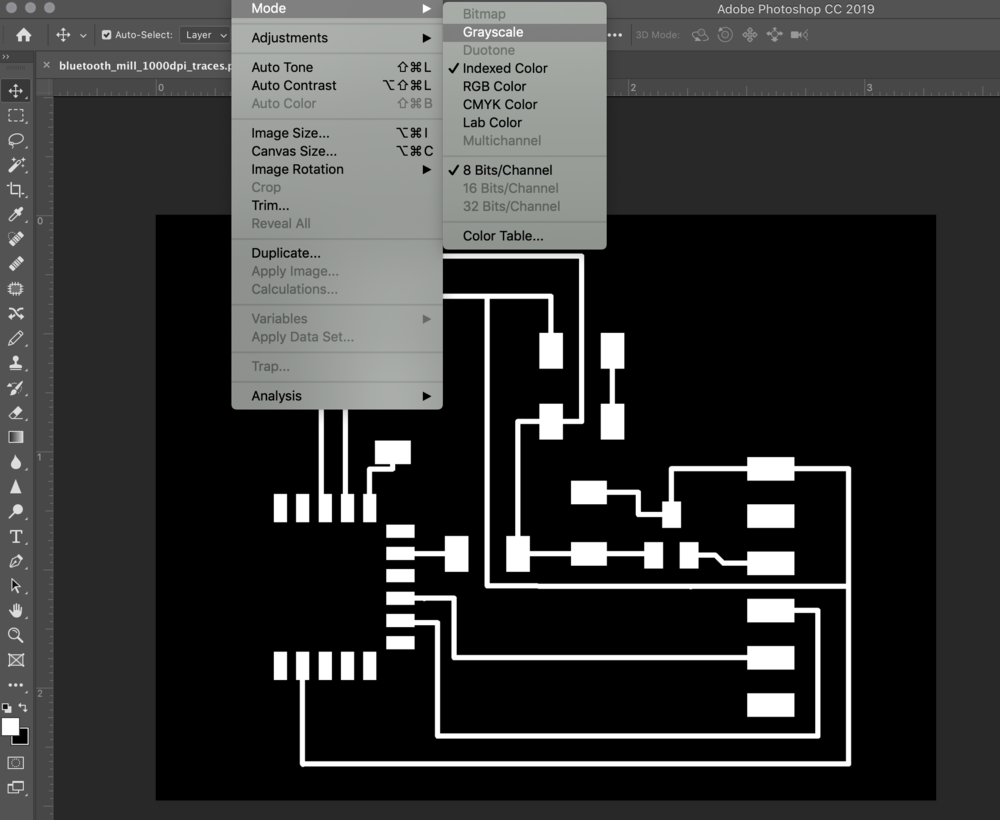
Changing image color mode in PS
As always, I had to change the image mode to grayscale in Photoshop to be able to add text and edit the 1000 dpi png exported from Eagle.
Milling & soldering
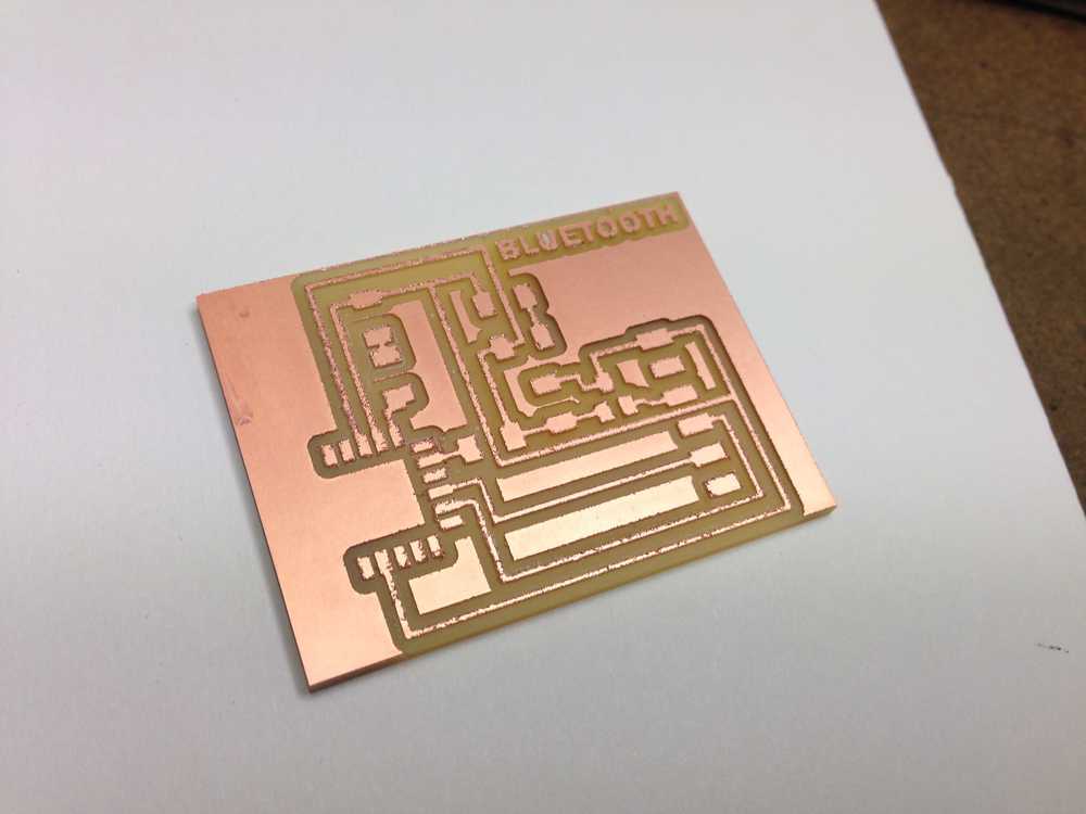
Milled traces
Milling is never completely uneventful; this time, the traces turned out very uneven, probably because of a somewhat split endmill.
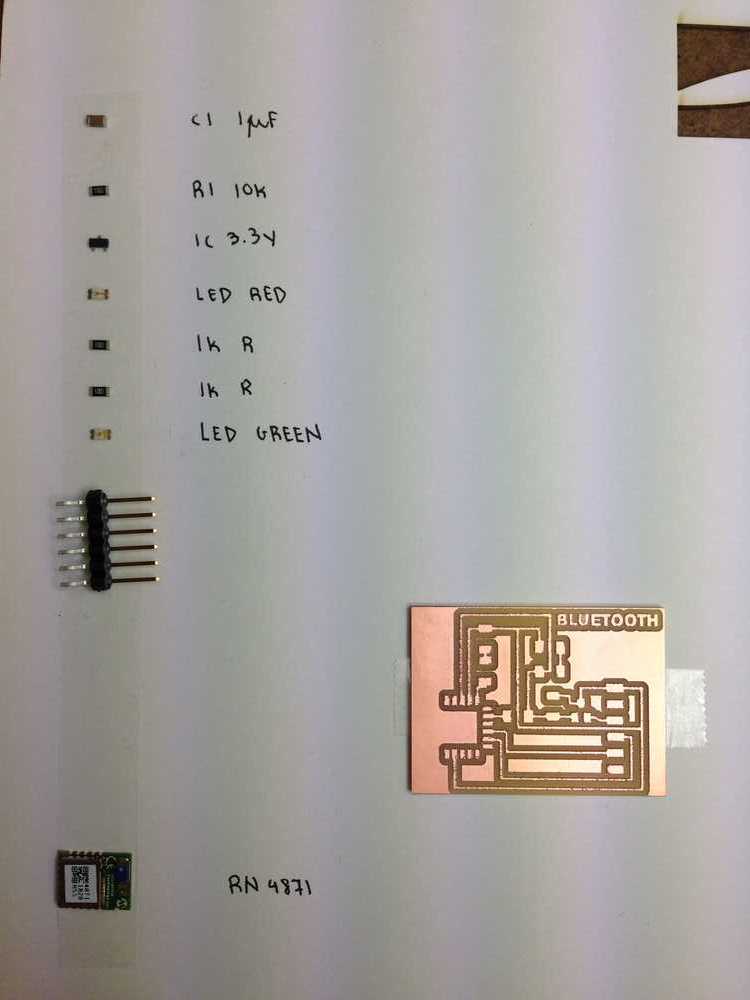
The components
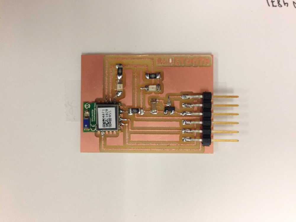
The soldered board
Soldering the Bluetooth unit was particularly difficult, and I'm not sure if I did it correctly.
Communication
Soldering the Bluetooth unit was particularly difficult, and I'm not sure if I did it correctly. I followed Rodrigo's and Rob Hart's steps and used Bluetility and LightBlue Explorer to try to connect to the board, but while the red light was constantly on when I connected the unit via the serial cable, the board wouldn't show up among the list of devices. I did have a BLE device appearing on my screen once, but I could not establish a connection with it. I resoldered the Bluetooth unit as well as the 10 k resistor, and I removed some extra copper from my board to make sure that wasn't interfering, but no luck.