Week 11: Machine Building
Overview
The machine building assigment was a group project rather than an indivisual project. The CBA, Architectue, and Harvard sections each had to build one machine. I was in the CBA section. The project our group decided to make was a cake-licking machine, that selectively removes or rearranges the frosting on a cake as a means of aesthetic manipulation. This can be used to render text or simple vector images on the top surface of the cake. The cutting tool is chosen not for accuracy, but rather the artistic merits of its dynamics. The full descirtiption of the machine and the workflow can be found at http://fab.cba.mit.edu/classes/863.15/section.CBA/cba-mtm/index.html
Kick Off
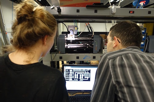
We began this project by first creating the mechanical stages that would provide the motion for the machine. These stages were the same for each group and the desing files were provided to us. During our first group meeting we fabricated the stages. Each person of the people had a particular task assigned. Myself and Caroline took the electronics fabrication tasks. We milled the PCB to which the USB and power cable are attached and then we solded the components and cables to the board.
In addition, we also prepared all of the cables that were going to be required for communication between the Gestalt boards
Other members of the group took other jobs and by the end of this three hour workshop we had the stages fabricated and assembled.
Frame Team
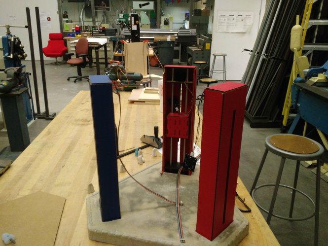
Following our kick-off event, we scheduled a couple of meetings during to decide what machine we were going to be making and how to distribute the workfolow. During one of those meetings, we decided to split ourselves into 4 teams - Tongue Team, Frame Team, Arm Team, and Software Team. I was in the Frame Team, whose other members were Kim, Vera, Harpreet, Raphael, and Yasushi. Our responsibility was to determine how the machine should look, how the stages should attach to each other, and to fabricate or or purchase the parts necessary for attaching the stages. Thanks to input form Eric, our team decided to make the machine as a DeltaBot, which turned out to be a very straight forward design mechianically. All we had to do for for a DeltaBot desing was to attach 3 stages facing one another. We desiced to cast the bottom platform out of hydrostone for sufficient support into which the 3 stages would be inserted. And for the top, we chose to make it out of cardboard.
My responsibilities as part of the Frame Team was to work on the design and making of the top, take accurate measurements for of each of the stages for both top and bottom, and to work on cable management if necessary.
Together with Yasushi, we measured and recorded the dimension of each of the 3 stages - on a all sides. Since the stages were made out of cardboard, they did not have exactly the same dimensions. Neverthelss, the difference in lengh, width, height, or other dimension between stages were only a few millimeters. There were also differences between lenth and width at the bottom versus the top of the same stage. That difference was also no larger than 2 millimeters.
Based on those measurements, Yasushi and Rafael made a CAD model of the Frame, which is shown below.
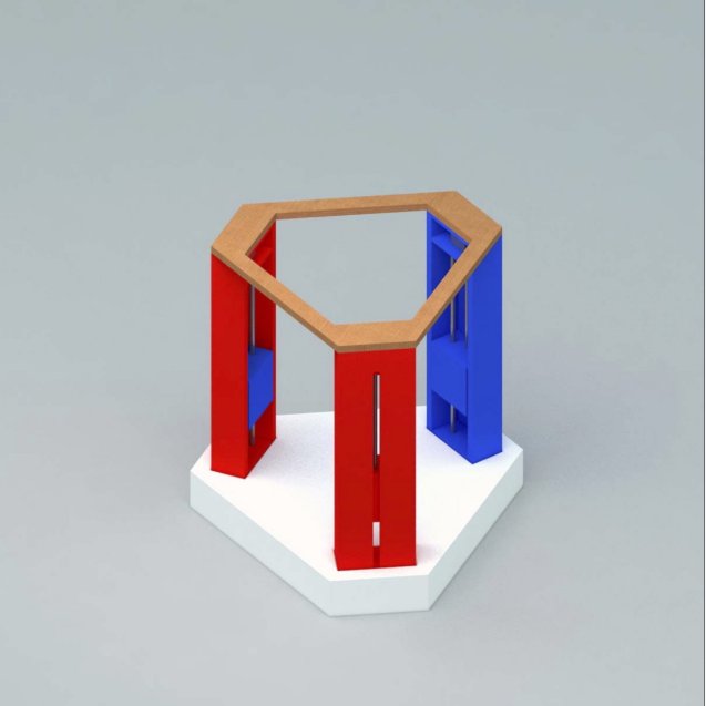
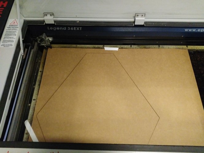
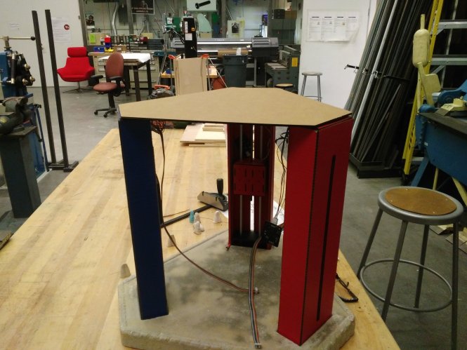
After the 3D model was Made, I and Harpreeet worked on making a model for the top of the machine. We decided that we should not be having a hole at the center, because that might not provide sufficient support. Thus, we modeled the top as a flat sheat that would attach to the 3 strages. Finally, we laser-cut it out of cardboard.