Week 8: Output Devices
I was very excited about this week, because this was going to be the first time in the class where we were actually going to transfrom code into something physicial other than flahing lights. Thus, what I ended doing was mill, stuff, program, and try out nearly all of the boards provided on the course website. The boards I made were for controlling servo, unipolar stepper motor, bipolar stepper motor, servo motor, LCD, and video.
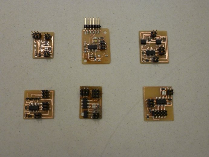
I wanted to try out all of the boards I had milled, but I did encounter some problems with some of boards. In particular, I was not able to program the unipolar stepper board and the video board, because I kept getting an rc-1 error message whenever I tried flashing a program to the ATTiny chip. For the case of the LCD board, I also encountered some problems. It programmed successfully, but when I tried connecting an LCD screen, nothing would shop up on the screen. I attempted chaning the code a few times and reprogramming it but nothing seemed to work.
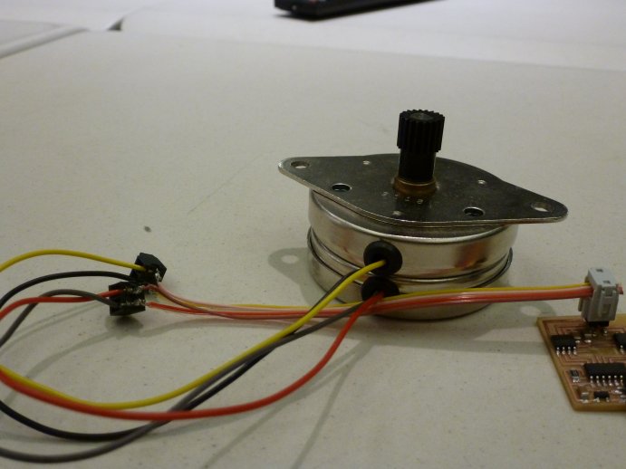
Then I moved on to the bipolar stepper motor board and with it I had a much better success. I was able to get it programmed and it allowed me drive the motor. Since I had worked with with steppers for a long time, I already knew how they work and how they are controlled so I could fairly easily understand the schematic and the purpose of each component on the board. For that same reason, I did not spend much more time with the stepper and moved on to the servo control board
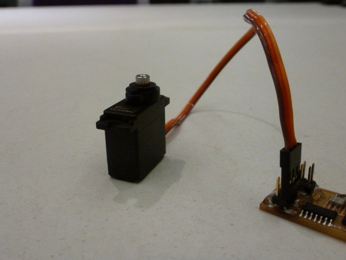
I had played with servos only once or twice in the past, and I knew that they were controlled using PWM. But I had forgotten the details of the relationship between the servo angle and the PWM signal. This served me as a reminder for some of the things I had forgottend, and I also learned a few new things about servos. Moreover, because I previously had not done any project that involed a servo, I was very much interested in making a servo based project. I wanted to use a servo motor as a display for some reading that I take with a sensor. However, because sensors were going to be cored in the upcoming week, I decided to postpone that project for next week. Thus, what I did for this week was simply upload the provided servo driving code, and make a few modifications to it to observed the behavior of the motor.
An important realization I made during this week is that it actually is not necessary to make a new board for each new kind of device that I wanted to drive. I realized that it must be possible to make a universal board based on the ATTiny44 that is capable of driving any of the devices. I decided to see whether I could make such a universal board. I decided to make an arduino-like board but for the ATTiny44 rather than for the ATMEGA328p. I based my design on the servo motor driver board, because it had all of its analog pins available and accessible, and the servo outputs were take from digital I/O pins. After numerous iterations on the design of the board, and after a number of boards I milled, I finally arrived at a design I that was functional and that I loked. (UPDATE: During weeks 9 and 10, I made yet another set of improvements to the design of my universal board.)
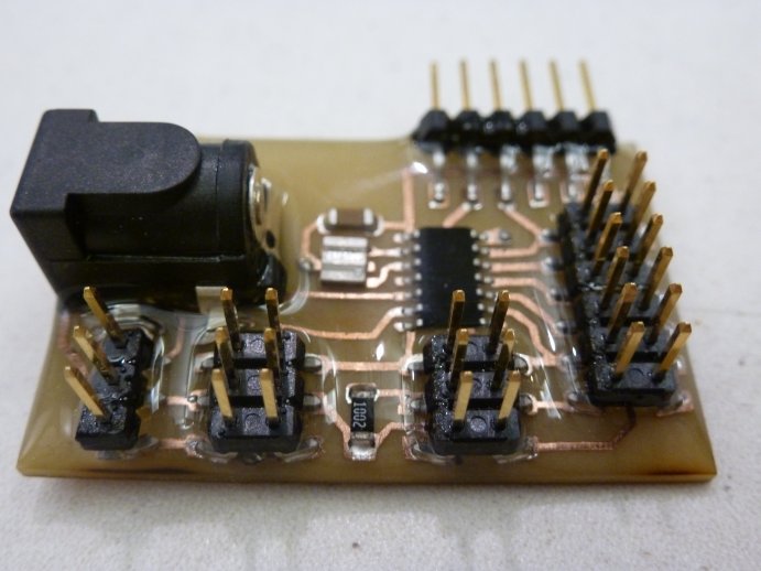
The board has support for up to 3 servo motors, which would connect to the pins on the left side. It can also support up to 6 additional devices, which could connect to the right side of the board. The left-hand-side pins on the right-hand-side pin column are all I/O pins (some of which support analog input), whereas the right-hand-side pins on that colum are all ground. To made the board truly universal, I also added a DC power jack, so that once programmed, the board can be powered without the need of the FTDI cable.