Week 2: Making the FabISB programmer
The FabISP is a programmer based on an ATTiny microcontroller, and allows one to program other microcontrollers. The assigment for this week was to build the FabISP, involves (1) Fabrication of the PCB, (2) Soldering of the SMD components, and (3) Programming the programmer.
Analysys of the Circuit
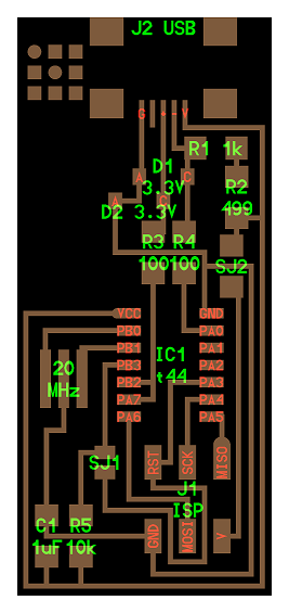
The image above shows the traces of the fabISP that we are going to be making, and it also shows which componets go where. Let us take a closer look at the schematic and try to make some sense of what is on this board.
In order to make the FabISP into a programmer capable of programming other boards, we must first program it with another programmer. But after we make it a programmer, we then want to disable the possibility of reprogramming that programmer. The circuit shown above is designed in this way. There are two solder jumpers, which when connected make the FabISP vulnerable to being programmed. When disconnected, the FabISP can not be programmed by another programmer. Let us look closely at what those jumpers do. One jumper establishes the connection between the Vcc pin on the 6-pin header and the rest of the board. When this pin is connected, an external programmer can power the FabISP and potentially program it. When it is disconnected, the board can only be powered through the USB port. The other jumper connects the reset pin on the 6-pin header to the reset port on the chip. When this jumper is removed, it becomes impossible to reset the ATTiny through the 6-pin header, and therefore impossible to program it throug that port.
PCB Fabrication
The firs process in making the FabISP was to mill a printed circuit board. A training was provided on Thursday about how to use Modella milling machines at the Media Lab for the purposes of milling PCBs. The projecc is relatively simple but contains some cirically important nonobious steps.
- Check the sacrifical layer on the bed of the machine. If it is worn out, replace it with a new one.
- Put double-sided tape on the entire bottom of the stock material you will be using to mill your PCB.
- Place the stock material on top of the sacrifical layer, and apply pressure on it until the taped side is firmly secured to the sacrifical layer.
- Attach the 1/64 inch endmill to the machine for milling the traces.
- Prepare the PNG files (traces file, and outline file) for the board you want to mill. The files for the FabISP can be found at the bottom of this page
- Open up Fabmodules.org
- Click on "Input Format" and then go to "Load Settings".
- Select the settings file that is on the Desktop, titled "LOAD_THESE_SETTINGS". (very important!!!)
- Click on "Input Format" again and now choose "Image(.png)", then load the image with the traces.
- Click on "Putput Format" and choose "Roland mill (.rml)"
- Click on "Process" and select "PCB Traces (1/64)"
- On the right side of the screen, select the appropriate dpi for your file if not already correct.
- For Output Machine select "MDX-20"
- Now look at eh machine and if the View light is on, press the View button on the machine to exit view mode.
- On the computer, now click "Move to xyz0" and this will move the endmill to the default position x=10,y=10
- Change the values for x and y and press the move button again until your find the coordinates for the lower left edge of your stock board.
- Once your have zeroed the x and y coordinates, you will zero the z coordinate. To do so, press and hold the down arrow on the Modella machine until the endmill goes down to about 2-4 mm above the surface of the stock.
- Carefully loosen the set screw holding the endmill and let the endmill drop until it hits the top of your board. (Be careful not to break the endmill's tip during this process). Tighten the setscrew.
- On the computer, press "Calculate", and inspect the calculated result making sure that there are no connected traces where there should not be. If so, then press "Send" and this will start the milling process. Otherwise, go back and edit the .png file to make the separation between the connected traces larger; then redo the process outlined here.
- After the job completes, vacuum the area and inspect the traces.
- Next you will load the .png file containing the outline and follow a very similar approach to the one for the traces, excpet that now you will use the 1/32 inch endmill, and in Fabmodules you will select the corresponding "1/32 Outline" option.
- Vacuum the area after the job completes and remove the board from the machine.
- Use sandpaper to debur surface of the board until the edges of the traces become smooth.
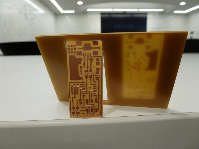
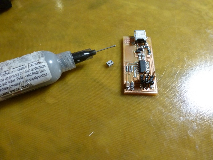
After going through all of the aforementioned steps, here is my resultant PCB.
Soldering
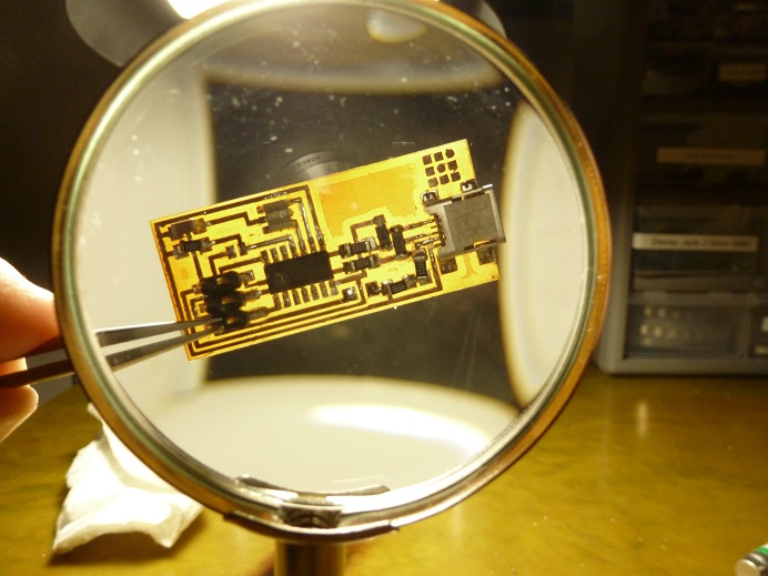
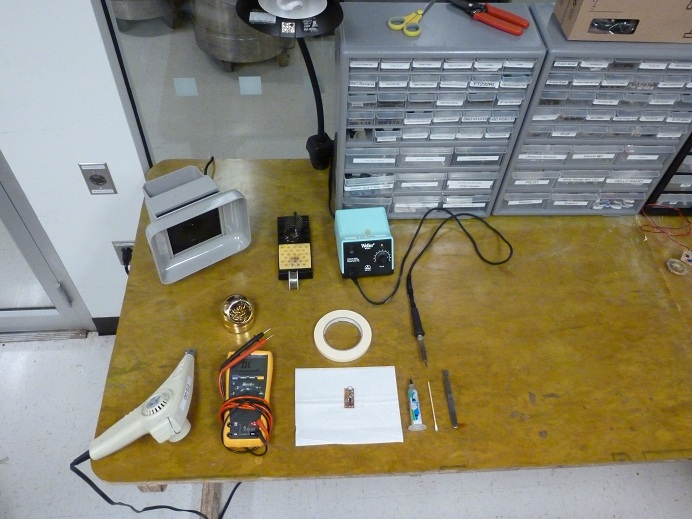
I have done soldering for many years, so this part of the process was not new to me. Nevertheless, one of the most important realizations I made while working on this how critical it is to prepare all tools and all components before you start soldering. I used a combination of solder paste and regular solder to complete the job. The paste was critical for soldering the 20MHz resonator to the board.
Programming the ISP
You will need a preprogrammed ISP or a commercial programmer to program your newly created programmer. In addition, you you will need a USB to mini-USB cable and a computer. Then you can follow this amazing Tutorial to get the board programmed. Once that is finished, remove the 2 jumpers and now the programmee has been transformed into a programmer.