Week 7: Embedded Programming
Overview
Objectives
Program your board from Week 5 to do something.
1.Designing a new board
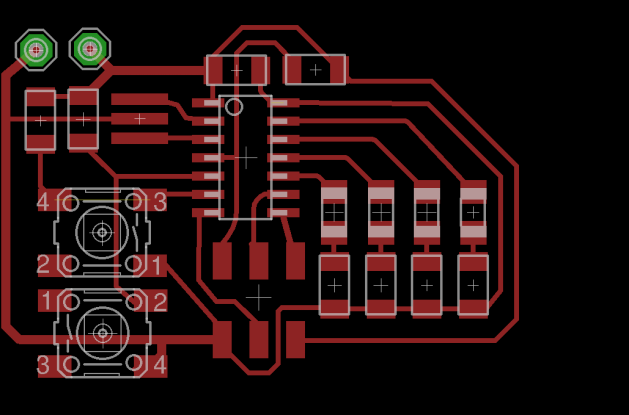
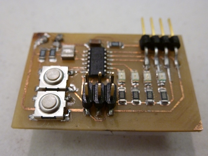
I wanted to program my board to do something nontrivial and exciting. However, since the board I had previously made had only 2 LEDs and one button, the range of possibilities was very limited. Thus, I decided to design a completely new board that has 4 LEDs and 2 buttons. In addition, I also added two additional pins to the design to allow powering the board from a battery.
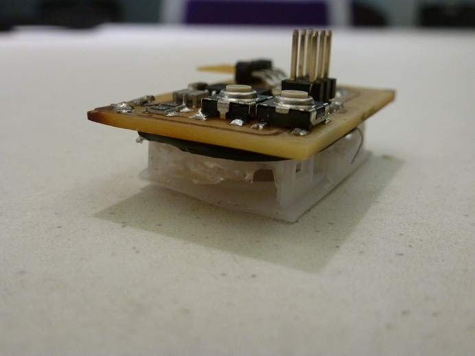
The pads with holes connecting to GND and VCC are on the upper left corner. Wires connected to the pads and going through the holes to to the opposite side allow battery to be attached to the back side of the board.
Tutorial for Programming the board
Part of the process for programming the board is explained in this tutorial and another part in this one. Below I provide a unified tutorial that coherently synthesizes and augments the information from the the aforementioned posts.
- You will need a FabISP that has been programmed already. See Week 2 for instructions about this part.
- Prepare your Linux machine by installing the required drivers as follows: Connect FabISP and the board using the 6-pin ports, oriented such pin numbers on the two boards coincide.
- Connect external power of about ~5V to the board (USB works great).
- Run the following commands to install the required drivers on your Linux machine, then reboot:
- Put the .make file and the .c file in the same folder. Open the .make file and in it type the appropriate name of your .c file.
- Connect the FabISP to your Linux machine, and run the following commands to program it
- make -f myFile.make
- sudo make -f myFile.make program-usbtiny-fuses
- sudo make -f myFile.make program-usbtiny
Programming and Using the Board
The main program on the board is an up-down mod16 counter that is controlled by the 2 buttons. When the UpButton is pressed, the counter increments by 1, and when the down button is pressed, the counter decrements by 1.
Moreover, there is an entire state machine with 3 states implemented in addition to the counter. The state machine is accessible when the two buttons are pressed simultaneously. The first time the user presses the two buttons together, the LEDs will automatically count count from 0 to 15. When the buttons are pressed together for a second time, the the same would occur but in reverse. And finally, when the user does the same for a third time, the user will access the 3rd state of the state machine, which is also the Easter Egg, where the LEDs will flash in a random pattern.