Week 12: Final Project
What I intended to do for my final project at the beginning changed over the course of the semester after the realizatin that the goal of the final project is integration of all of the skills covered in the course rather than focus on one particular skill.
Energy savings is a big buzz-fraze in the modern days, so I wanted to make a device that would help reduce energy consumption. During the winter, the temperature inside the home is typically kept higher than the temperature outsize, and similarly, duirng the summmer the temperature inside is typically kept lower than the temperature outside. However, there are certain days, or certain times during a day, when the perceived temeprature outside is the same as the perceived temperature inside, and during those times/days energy savings could be achieved by turning off the AC/heater in the house and opening a window instead. The challenge, however, is knowning when those time windows occur. Thus, I decided to make a device that attempts to address this problem. I made a automated window that responds to differences in perceived temperature (heat index) between the enviroment inside the house and the external environment, or between the external environment and a preprogrammed perceived temperature.
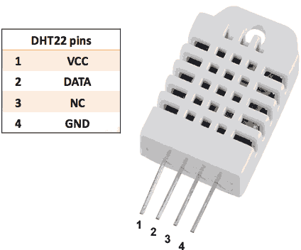
I approached this project from the electronics side first. My initial plan was to use only 2 temperature sensors that monitor the temperature inside and outside the house and then to perform an action based on the comparison between them. However, after further consideration, I realized that a more appropriate comparison would be the heat-index - or the perceived temperature, which is a function of both temperatuer and humidity - rather than the actual temperature. Therefore, I needed to be able to measure both temeprate and humidity. Hence I bought two HDT22 temperature and humidity sensors to accomplish this goal.
I was planning to use my ATTiny44-based universal board from week 10 for this project. However, I soon realized that it would be next to impossible, because the library that comes with the DHT22 is incompatible with the ATTiny44, and writing my own library would have taken several weeks. Thus I had to seek an alternative solution. I had to either use a different sensor or a different microcontoller board.
The decision I made was to design and fabricate my own arudino compatible board based on the ATMEGA328p microcontroller chip. This was going to allow me to use the DHT22 sensors and the corresponding Arduino library. Moreover, I was then going to be able to do the programming during standard arduino commands as opposed to AVR-C commands.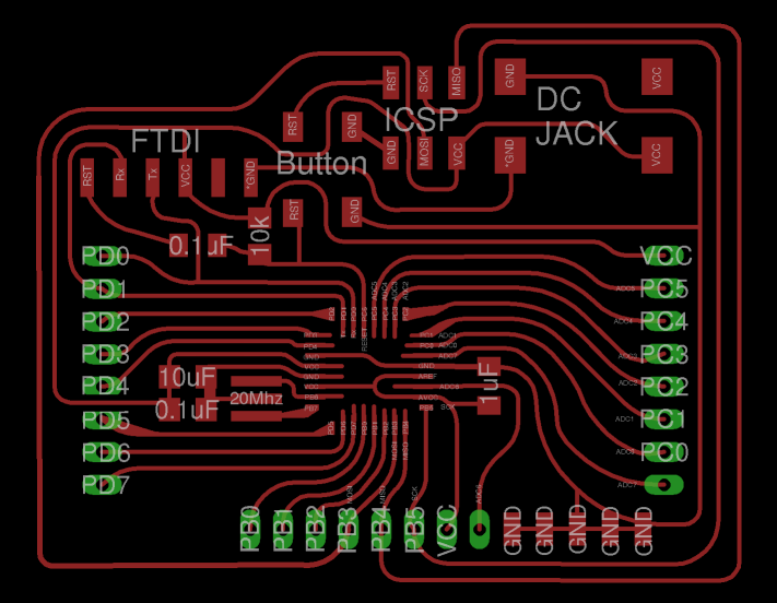
Eagle design files: DriverBoard.brd, DriverBoard.sch
PNG files for milling: AliDuinoTraces.png
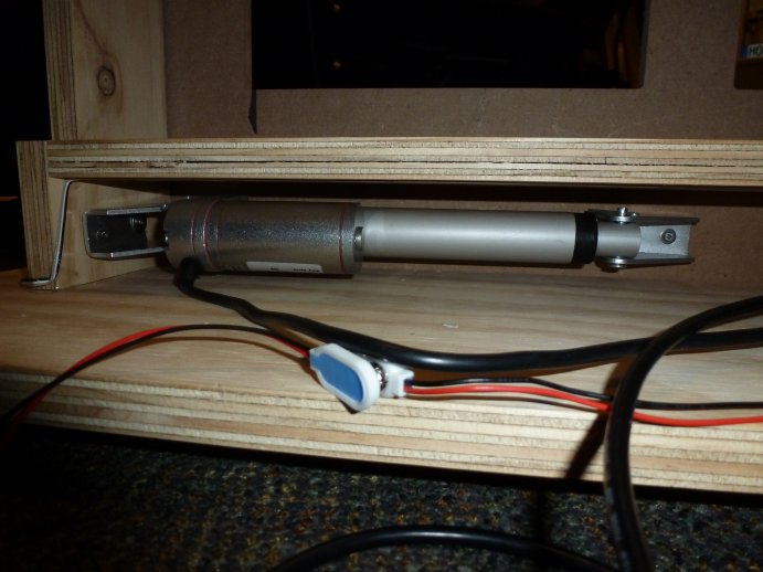
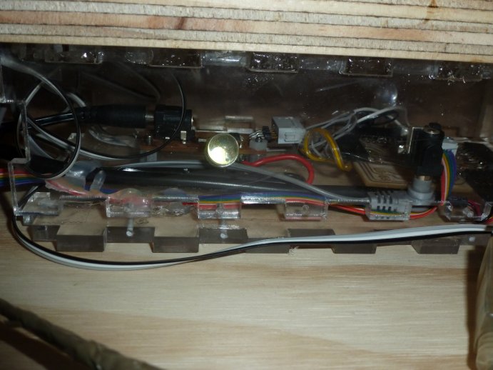
Another board I had to make was for powering the linear actuator. I tried using the H-Bridge IC in the inventory (Allegro A4953), but after milling and fabricating a board for the H-Bridge, it was not able to drive my actuator. It could not provide enough current to power the actuator. Nevertheless, thanks to Eric's suggestion, a 0.1 ohm resistor fixed the issues I was having. The chip has a built-in current limiting protection circuit, and after a certain default current level is reached, the chip shuts down. Hidden deep in the datasheet, however, there was information about how to increase the current limiting threshold with a current sensing resistor attached between the LSS pin and ground. Based on the equation in the datasheet, I calculated that I would need a resistor of 0.25 ohms maximum in oder to prevent the device from shutting down during startup of the linear actuator (which is when the actuator consumes most current). After adding a 0.1 ohm resistor for current sensing, my problems vanished - almost. The circuit was still not being able to power the actuator propery. Another suggestion I got from Eric was to measure the resistance between the terminals of the linear actuator. It was only 2.5 ohms, which then immediately explained why I was unable to drive the actuator even when I had set the current threshold limit very high. With a starting resistance of 2.5 ohms and driving voltage of 12V, the actuator was requiring 4.8 Amps of current at startup. I had to reduce the statup current requirement, which I was able to achieve by adding about 5 ohms of resistance in series with the actuator. But my first attempt of adding a 5 ohm resistor went up in smoke - literally - when the resistor just burned out after only 10 minutes of use. What I then did was replace the 5 ohm resistor with two parallel connected 5 ohm resistors in series with another set of 2 parallel 5 ohm resistors. The parallel components were placed on top of one another, rather than on a separate pad as indicated on the schematic. This distributed the power dissipated to 4 different resistors as opposed to a single resistor. After this change, the board worked flawlessly.
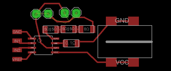
Eagle design files: DriverBoard.brd, DriverBoard.sch
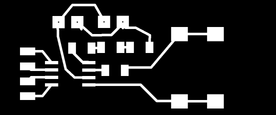
PNG files for milling: Traces.png, Outline.png
Making a box to house the electronics
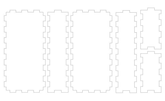
I found a piece of acrylic in our lab and decided to use it to make a box for the electronics. For the desing of the box I used the web-based tool boxmaker which automatically generates a box desing.
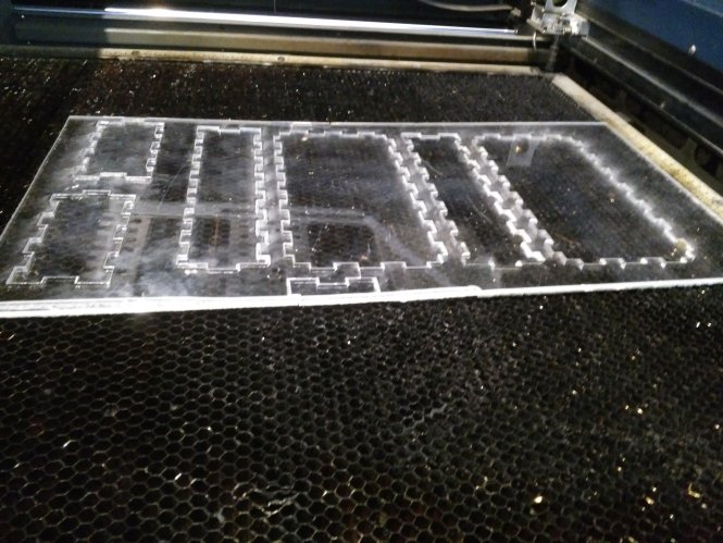
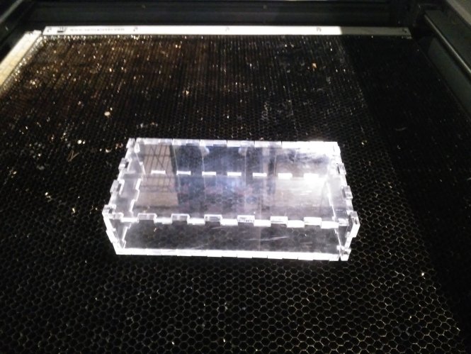
I then laser-cut the pieces. The laster-cutting process was not easy. I used the suggested settings of 100% power, 5000Hz frequency, and a speed of about 15-20, but in order to cut all the way through the acrylic (about 0.75cm thick) I needed to do 5 passes with the laser. The most challenging part here was determining whether the acrylic has been cut or not after each pass. It was not possible to test by touch because that would move the material, which would make it impossible to realign in the same position. What I used for a guide, therefore, was an optical technique. I noticed that while the acrylic is being cut, there is no reflected light. However, once the the material has been fully cut, then light from the laser reflects off the bed of the machine. Thus, I determined that the number of passes needed to fully cut the acrylic is 5 (or actually 4) based on the fact that on the 5th pass I could see reflections while the laser was moving along its trajectory.
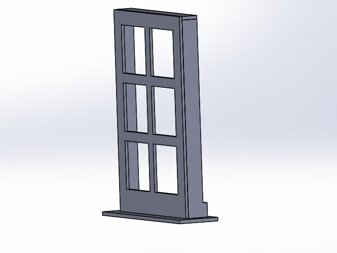
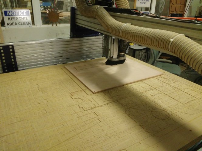
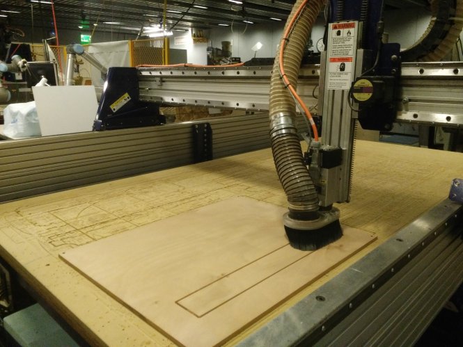
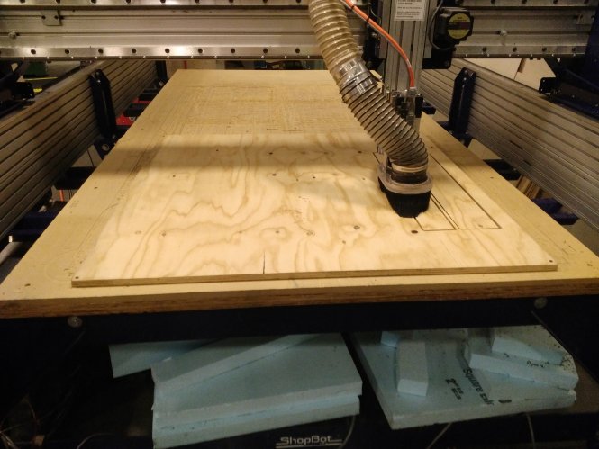
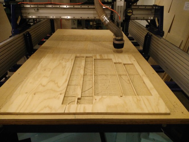
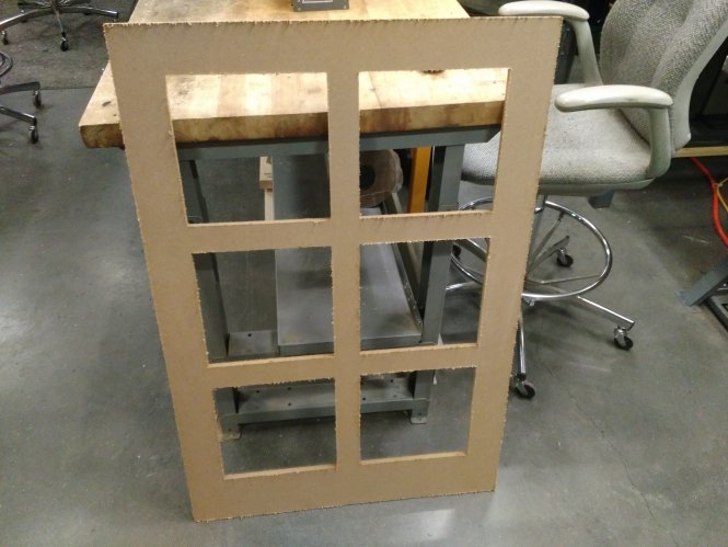
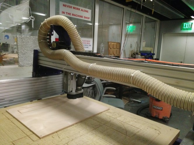
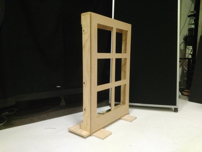
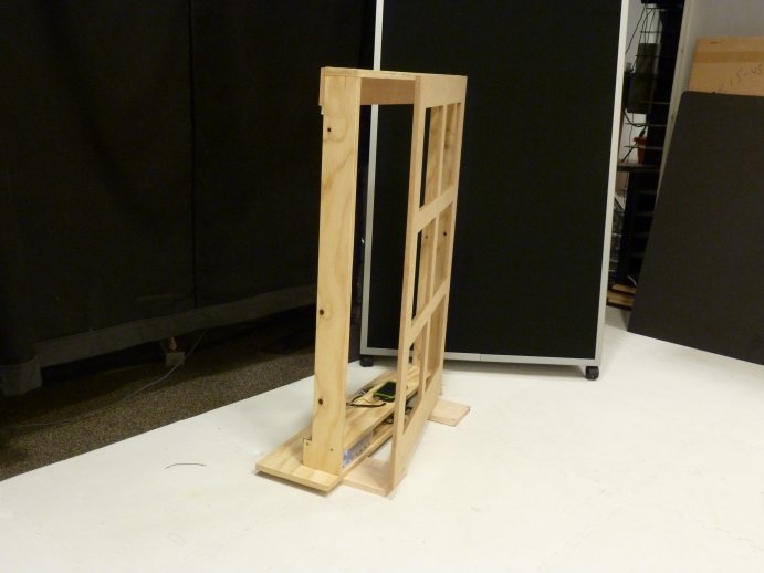
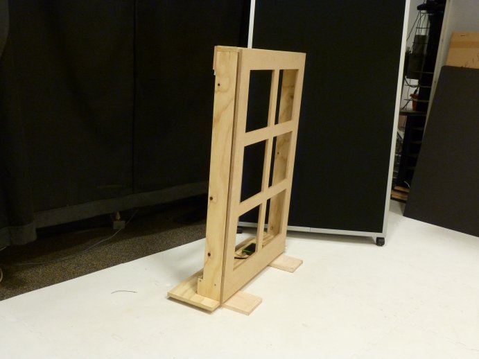
Modeling and Building the Window Frame
This part is documented my Week 4 page

Putting everything together
Programming
The computes the heat-index based on temperature and humidity measurements from each sensor. It then takes the average value of 5 readings and compres the average heat-inside inside the house with the average heat-index outside the house. If the difference is greater than a threhold value of 0.8 degrees C then the window opens if its initial state was closed. If the present state of the window is open, and if the diffrence in avereage heat-index between inside and outside is less than -0.5 degrees C, then the window closes.
Control CodeBill of Materials
- Linear Actuator - $55
- Solar Charger (optional) - $22
- Plywood - $20
- Arcylic - $0
- DC-DC Boost Converter (optional) - $8
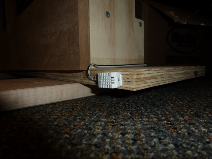
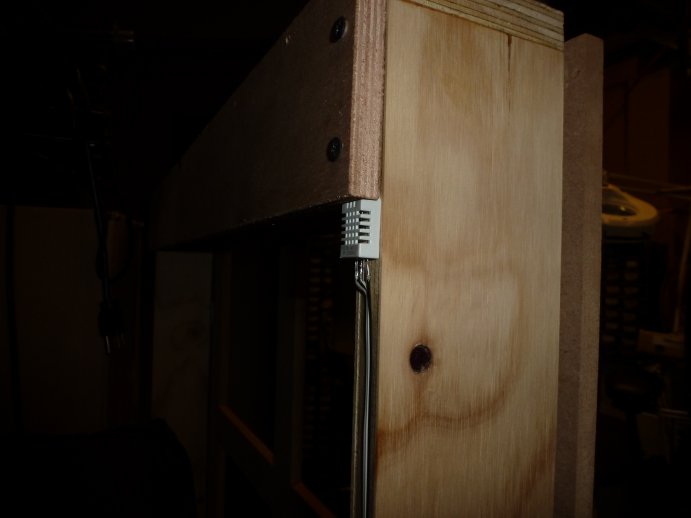
- Two DHT22 sensors - $18
- In-house electronics parts - $10
TOTAL: $133.00
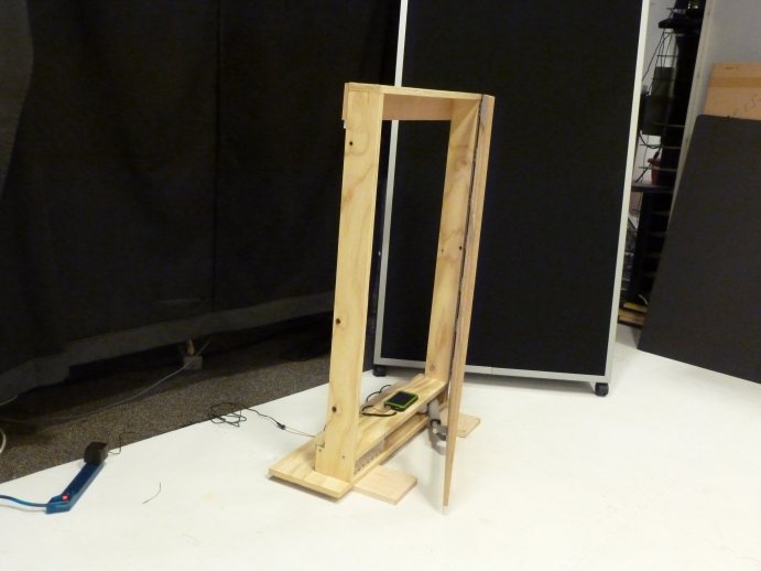
End Result
Future Work
There is a variety of features that could be added to the project. One particulary useful feature would to be add a knob or other control mechanism so that the user can also set the desired perceived temperature to which they wish to compare the perceived temperature outside. Another one would be a display that displays a history graph of the humidity and temperature measurements indide and outsde during the entire day. If a user has a visual indicator of how temperature and humidity varies during a day, then an interesting change of user behavior might be observed with respect to how the user chooses to set the temperature inside the house. Yet another feature would be make the system remotely controlled either through WIFI or bluetooth.