Ben Z. Yuan - How to Make Almost Anything
Week 2: Computer-Controlled Cutting
This week
We learn how to use a vinyl cutter and a laser cutter, and design and assemble a press-fit construction kit.
Vinyl cutting
The EDS lab has access to a Roland GS-24 vinyl cutter capable of cutting fairly intricate designs in vinyl. CBA has created a toolchain allowing essentially arbitrary PNG files to be converted to usable toolpaths for the tool.
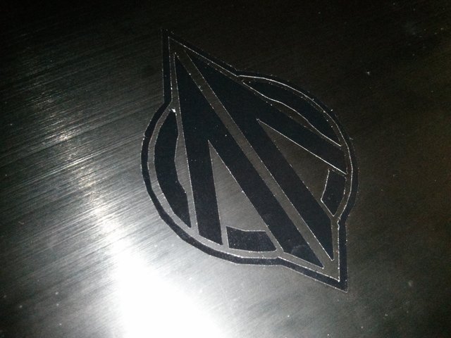
Our individual assignment this week was to use the vinyl cutter to cut something. As laptop stickers were popular items among the group, I decided to create one as well, and augment my laptop with the logo of Anvil Aerospace, my favorite Star Citizen ship manufacturer.
![]()
Battlefield player “Kruzil” has created a version of the logo without text (which would be useful for a first iteration, as I anticipated the lettering would be challenging to deal with):

Inverting and processing this logo allowed the CBA toolchain to create a toolpath for the vinyl cutter, which successfully cut the logo from black vinyl. After carefully removing the cut vinyl from the stock and pruning away the negative space, I was left with this nice decal:
Regrettably:
- This is black vinyl on black plastic - granted, the vinyl is much shinier than the plastic, but the decal might be hard to see from distance.
- Which is all well and fine, since because I’ve never applied a laptop sticker before, I installed this decal “upside down”. Oops!
I might fix all that later, I think.
Laser cutting group project: characterising the laser cutter
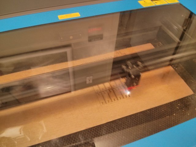
The EDS lab has access to two Universal Laser Systems laser cutting units, one with a 12” x 24” bed and one with a 18” x 30” bed, with CO2 lasers easily capable of engraving and cutting through cardboard and acrylic, as well as marking specially treated metal.
Our group project this week was to characterize important properties of this laser cutter. Our group took measurements of the laser cutter kerf (effective beam width) and also investigated how various power and speed settings affect the kerf. We describe our discoveries here.
The main takeaway is that the kerf is something like 0.02” no matter how you set the laser cutter. I use this number for the rest of the assignment, to useful effect.
Laser cutting individual project: parametric press-fit construction kit
Our individual assignment this week was to design and construct a parametric press-fit construction kit out of cardboard that can be assembled in multiple ways. Since it’s hard to imagine a useful enclosure (that can withstand being carried in a pocket or backpack) being manufactured with this technique, I elected to take this assignment very literally.
Meet Mr. Cardboard, icon of the Almightly Patron God of Making:
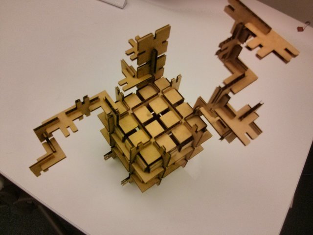
(Here he is looking noodly.)
What?
Mr. Cardboard is one of a Large Number (tm) of possible configurations of a kit containing the following pieces:
- 26 square panels measuring 2” x 2”.
- 25 I-shaped ligatures, 2” long and 0.73” wide.
- 7 X-shaped ligatures.
- 25 L-shaped ligatures.
- 17 T-shaped ligatures.
This is enough pieces to assemble a 2 x 2 x 2 cube, with additional ligatures that enable supplemental structure when incorporated into the construction.
Slots are sized to the material thickness (0.17” for the cardboard stock provided by EDS) and include a small amount of chamfer to ease the fitting process.
During the group assignment we determined that there was apparently some variation in the thickness of the pieces of cardboard stock provided by EDS; additionally, from the practical experience working with the laser cutter during the group exercise, it was known that some iteration of parameters was potentially going to be required. Hence, parametric design was a requirement; to adapt and tune the design to a different material, all that should be required is to tweak a parameter and regenerate the vector output, without other hand tuning required.
The OpenSCAD file lives here. See if you can spot the bugs! (A list of bugs I know about is at the end of the article.)
How?
It is worth noting that the laser cutter machines in EDS are set up with a job pipeline tuned to work with CorelDRAW. Time on the laser cutter is sparse when many people are trying to use it at once, leaving little time for alternate pipeine development – hence, an approach offering the least contradiction with the training was called for.
I elected to use OpenSCAD for this exercise. OpenSCAD provides both 2D and 3D constructive solid geometry with a mostly competent scripting language supporting many useful shapes and CSG primitives. It also handles export to a number of standard formats, like STL (which could be useful later) and SVG (which could be useful now).
The (required for usage!) scripting capability of OpenSCAD is key for this task: with judicious use of parameter definitions, we can retune the design in response to required changes without having to redraw each type of piece “by hand”.
Based on my experience with the group activity, for which I used OpenSCAD to generate a couple of patterns to cut out, I know that the following operational procedure Just Works (tm) with our hardware:
- Do the thing in OpenSCAD, respecting a linear scaling of 96 units per inch (this is a gigantic time saver!).
- Press F6 to render, then export to SVG.
- If there is engraving to be exported from OpenSCAD, it needs to be rendered and exported separately – at the same scale.
- Open the output SVG in Inkscape. Set the fill to empty and the outline to
full red (#FF0000). Save the SVG.
- Any additional SVGs containing engraving should be imported and overlaid onto the same SVG file; their outlines should be blue (#0000FF).
- On the laser cutter, create a new file and import the SVG. This should need no further scaling.
- Set the imported object outline width to “hairline”.
- Print!
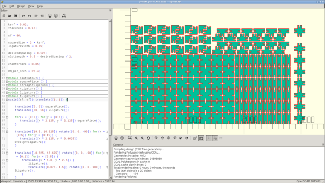
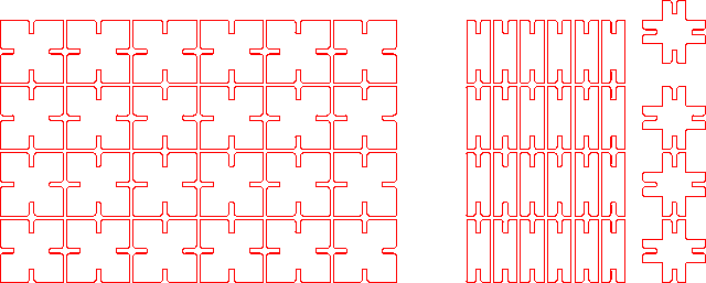
Here’s what I see in OpenSCAD (for a more ambitious layout that would have produced a 3x3x3 cube but needed the entire cutter bed to produce in one job):
To verify the mechanical properties of the pieces (and the validity of the production pipeline), I cut out a test pattern:

(These were very slightly smaller in outer dimension, by about 0.02”, than the nominal values, due to not remembering that kerf was a thing for everything that wasn’t the slot width. This doesn’t affect how they interface with the production pieces, as the slot widths are all correct and the same.)
The first time I tried this I ended up with pieces that didn’t fit together - because I had forgotten to adjust the material thickness from the draft thickness of 0.15”. Changing this to 0.17”, to match the measured thickness of the target stock, resulted in pieces that were mechanically compatible with each other - in both the test pieces and the final kit, the fit is very tight, but more than adequately usable for construction.
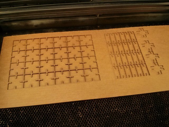
Despite scaling down the final production run, I still had to split it into two jobs (to fit on the available pieces of stock). Here’s the template for the first job:
(Notice the gap in the middle; I included it to skip over a fold in the underlying stock.)
Here’s that after being cut:
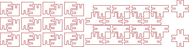
Here’s the template for the second job:
Assembling objects from the cardboard pieces has to be done with some care, as while the cardboard has good mechanical properties while intact, it permanently loses those properties along any folds, creases, or nicks that develop. The best way to do this is to construct individual pieces of the final product that can be connected to the larger structure being built by applying pressure in a single direction only.
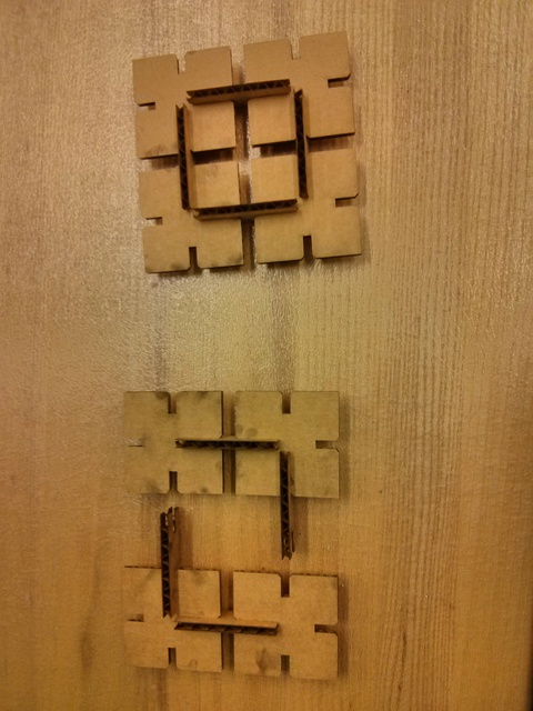
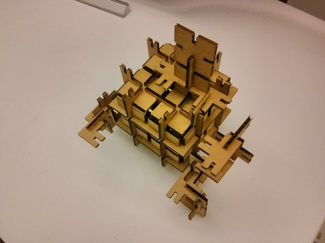
The pieces snap together nicely into panels:
Finally, here’s Mr. Cardboard resting (in a mostly non-noodly pose):
Known bugs
I discovered these later.
- The ligatures are 0.73” wide and not 0.75” as intended. This is because I forgot to define the kerf when setting the width of this part. This has no serious structural implications in practice.
- The chamfer size is slightly larger than the nominal request of 0.05”. This
is because the base size of the square used to cut the chamfer forgot a
multiplication by
1 / sqrt(2). The resulting chamfer is perfectly fine for assembly purposes. - The square parts that were part of the second test batch are smaller by 0.02” than the final production squares.