Ben Z. Yuan - How to Make Almost Anything
Week 8: Molding and Casting
This week
Vigilo Confido.
Individual assignment: make a mold and use it to cast parts
I decided for this week that I wanted to cast something with the logo of the XCOM Project on it, mostly because why not. I tracked down a high-resolution image of the logo (recreated by DeviantArt user Titch-IX), scaled it down, and tried to import it into OpenSCAD as a height map.
Unfortunately OpenSCAD melted when I did this.
Defeated, I turned to heresy again.
Windows partitions aren’t just for show – occasionally we have to use them to run software. In this case that software is Autodesk Fusion 360, a tightly integrated CAD and CAM suite that has no Linux build. As a student Fusion 360 is free to use; a subscription costs up to $1500 annually, but seems intended for those using the software to make money.
I used Hans Kellner’s Image2Surface script to do the import. After getting unsatisfactory initial results, I adjusted the image colors using GIMP to raise the interior field, and additionally added a Gaussian blur outline around the logo to create a sloped border. Here’s the heightmap I ended up importing:
![]()
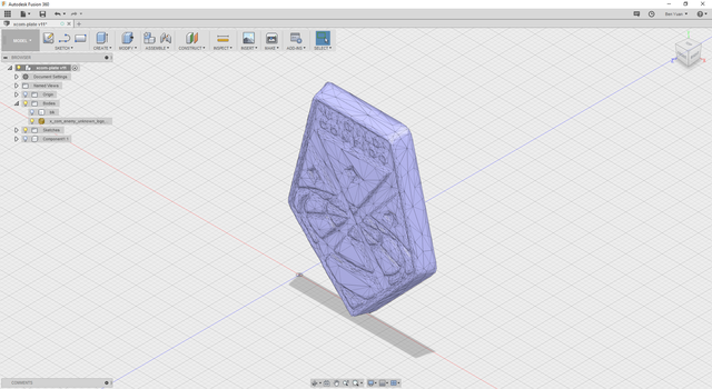
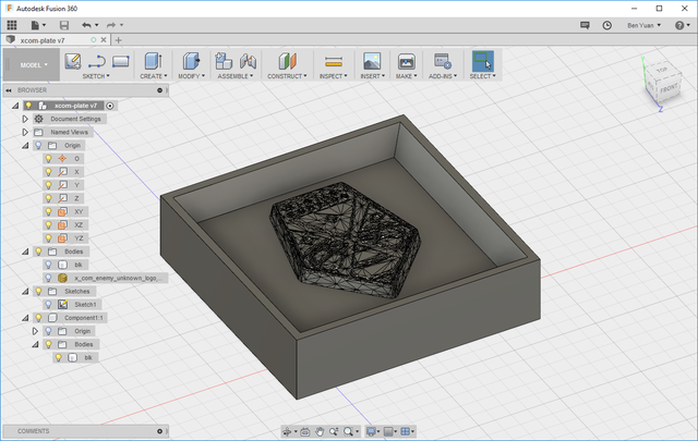
Importing this resulted in a mesh with far too high resolution to convert to a BRep for further manipulation. Luckily Fusion 360 now has a mesh editor, which I used to remove unwanted parts of the mesh and then simplify it to the point where this conversion was possible. This allowed a model of the mold container to be added around the part, creating one object suitable for machining.
In a fit of madness I tried out Fusion 360’s toolpath generation abilities. With the Othermill as a target machine, I created three toolpaths:
- An adaptive-clearing rough cut for a 1/8” flat endmill with a spindle speed of 16400 RPM and a feed rate of 1500 mm/s.
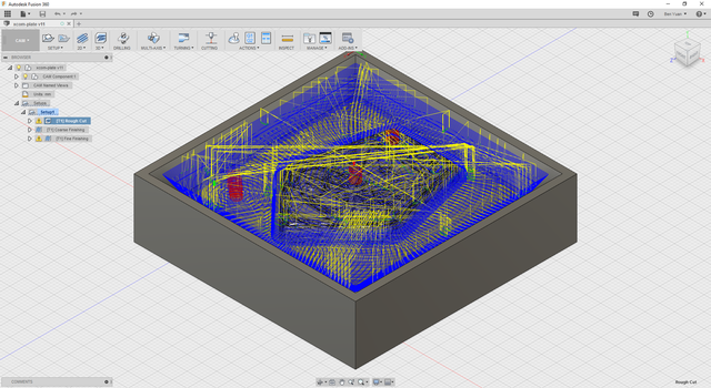
-
A parallel + perpendicular coarse finish cut for a 1/16” ball nose endmill with a spindle speed of 16400 RPM and a feed rate of 900 mm/s.
-
A parallel + perpendicular fine finish cut for a 1/32” ball nose endmill with a spindle speed of 16400 RPM and a feed rate of 600 mm/s.
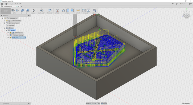
These feeds and speeds are adaptations of Bantam Tools’ more aggressive recommendations for machinable wax.
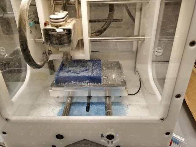
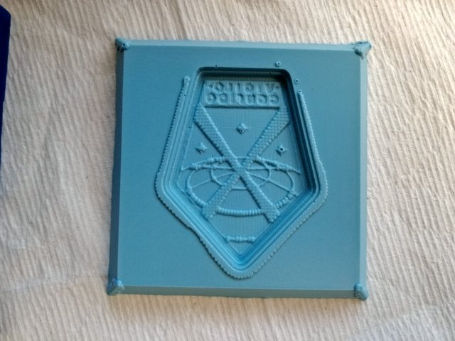
I exported these toolpaths as gcode and imported them into the Otherplan software, which happily cut them into a half-height (19 mm high) block of blue machinable wax. The full-height blocks (~38 mm high) crash into the OtherMill spindle housing, so I had to use a shorter block.
Here’s the result of that:
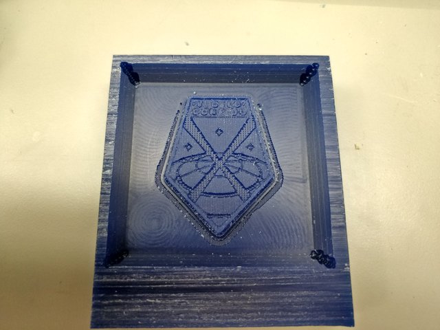
An unintended consequence of using ball-nose endmills for the finishing was the creation of a funny texture reminiscent of cloth. This could have been corrected with some adjustment of the toolpath but I decided to roll with it.
Another unintended effect was the creation of a partial “trim” border where the generated fine finishing toolpath decided to start cutting into the surrounding field before being constrained by my requested constraint border. I could have gone all out on this, potentially allowing the finished product to have a bit more physical depth, but elected not to as I was running out of time.
The next step was to use this wax positive mold to create a negative mold in silicone elastomer. We used OOMOO 25 for this step, which is very easy and safe to use (though not food safe).
I mixed appropriate quantities of the OOMOO 25 resin and poured it slowly into the mold, using a popsicle stick to scrape away the excess.
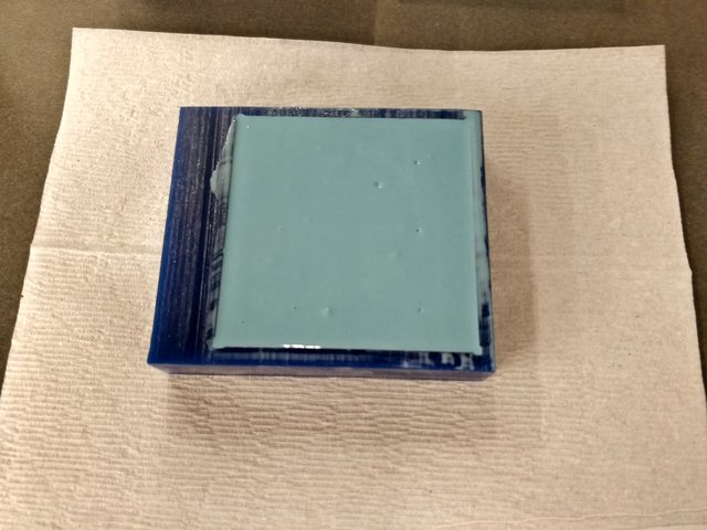
OOMOO 25 advertises a 75-minute cure time but I found this in practice to be closer to 2 - 3 hours before the mold stopped being tacky and was ready to be demolded.
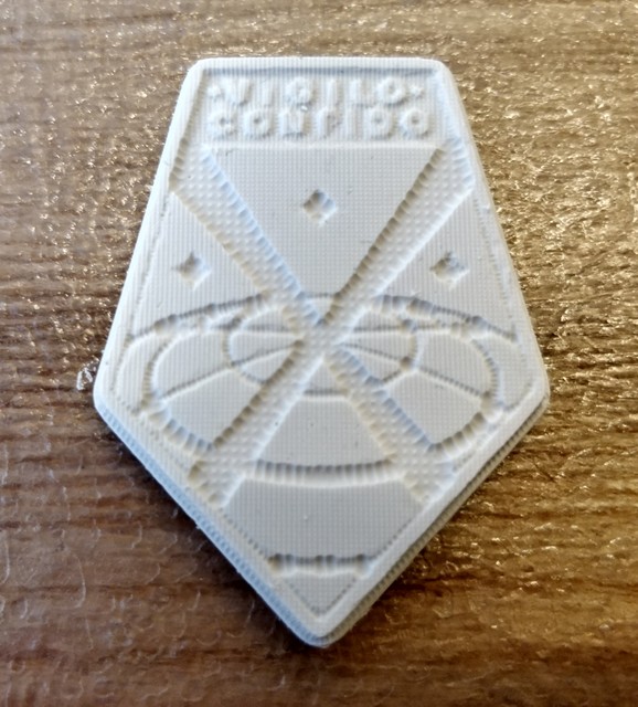
The OOMOO elastomer successfully captured all of the detail produced by the Othermill milling machine.
To produce the final part I used DryStone casting media, which is a high speed casting media containing plaster and small amounts of ethylene vinyl acetate. It took only about 40 minutes from pour time for the part to be ready to be demolded, leaving a nice token in the shape of the original logo.