Ben Z. Yuan - How to Make Almost Anything
Week 7: Embedded Programming
This week
Experiments in final projectness.
Individual assignment: program a board
Two weeks ago we had made a board, and I had gone ahead and programmed that one to respond to a button using plain avr-gcc. This week I decided to pick up and learn how to use some peripherals using the Arduino IDE and libraries.
Technically, output devices is in two weeks and input devices is in four. But if I want to get my final project completed on time I need to learn these things yesterday.
Test board: Teensy++ 2.0 (AT90USB1286)
The AT90USB1286, like the rest of the AVR family, is an 8-bit processor with a 16-bit address space and Flash / SRAM / EEPROM space measured in KB.
While I’ve been hard at work designing my final project board (which has required me to learn a two-layer PCB milling process, as it is unroutable on one layer), I determined that if I wanted to make useful progress this week I needed a suitable board to prototype on immediately. The Teensy++ 2.0 is the candidate here: it includes the exact microcontroller I’m looking to use in my final board design, and thus will be a good candidate as a programming target.
I’m told breadboarding is heresy. I claim it’s a useful way to speed up the prototyping cycle: the time it takes to reconfigure a circuit (e.g. to connect something new to an ADC, or switch a peripheral’s interface mechanism entirely) is much shorter on a solderless breadboard than on a milling machine, and EDS time is the scarcest resource we have.
The Teensy++ 2.0 ships with the Halfkay bootloader preloaded, and ships with a 16 MHz crystal. This is in contrast with the factory AT90USB1286, which ships with an Atmel-provided bootloader and set to accept an 8 MHz crystal. (The latter can be reset by any mechanism capable of setting fuses.)
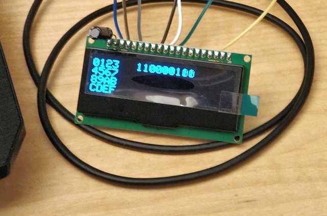
Display module: Adafruit 2.3” 128x32 OLED (SSD1305)
These are nice OLED displays, very legible from desktop distance, and a decent form factor. They’re driven by a SSD1305 OLED driver, which can speak SPI and I2C. They are 3.3 V parts, which means communication to a 5V board must happen through level shifters, and power must be provided by a voltage regulator.
The Adafruit SSD1305 library shipped with some bugs:
- Compilation error because of
#definein the wrong place in the splash screen initializer. - Initialization code was sending commands for the 64-row OLED panel rather than the 32-row panel, resulting in display garbage.
display()was resetting column offsets 4 columns in the wrong direction, resulting in a 4-pixel horizontal offset and losing 4 columns of usable space.
I fixed these problems and then had a beautiful Arduino library.
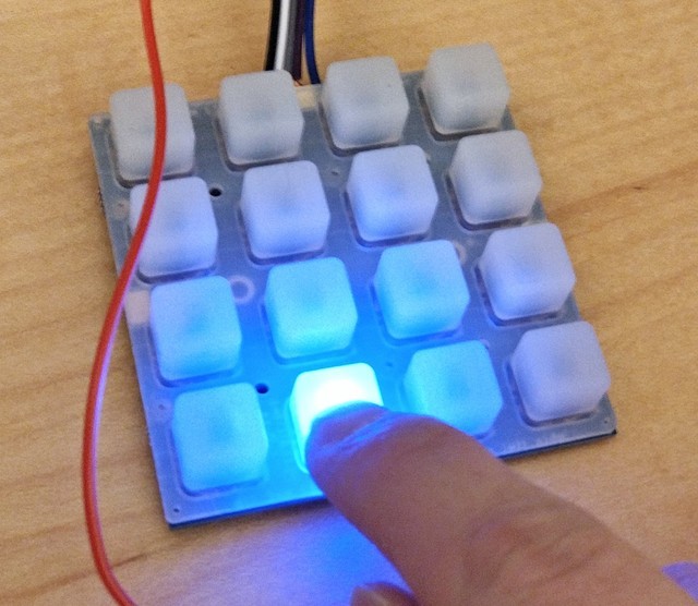
Keypad module: Adafruit Trellis (HT16K33)
These are a smallish PCB with elastomer button overlay. The core of the Trellis board is a HT16K33 chip, which is a combined LED driver and keypad scanner that speaks I2C. The board has slots for through-hole LEDs on every button, which can be independently addressed. Additionally, diodes prevent ghosting from multiple simultaneous key presses.
The Adafruit library for this board works out of the box, with quirks. I quickly discovered that external interrupt handlers can’t use the hardware I2C bus at all, because interrupts on AVR cannot be nested, so we can’t do keypad input at interrupt speed (and instead have to do it at main loop speed). We can still use the interrupt line to signal to the main loop if there are keys waiting.
(We also discovered somewhat later that a pause of 20 ms between keypad state polls is mandated, or else it becomes nearly impossible to determine whether keys are held down.)
Useful notes: Arduino
The ecosystem is a lot more convenient than avr-gcc: many batteries are included.
The Arduino IDE includes automatic uploading to anything speaking the Arduino bootloader. Teensy boards have the Teensyduino extension to the IDE, which includes support for Halfkay.
The Arduino standard library tries to hide a lot of platform specific details – sensible, as the ecosystem is supposed to run on a variety of architectures. However, it does not hide the avr-gcc standard library, and so direct register manipulation remains perfectly possible.
digitalWrite() and digitalRead() are extremely slow for what they do: they
add a lot of overhead doing sanity checks. In cases where output pins are not
dynamically determined, they could potentially be replaced by macros. Certainly
every instance of digitalWrite can be replaced by an instance of bitwise
arithmetic on the corresponding PORT register.
Unfortunately a lot of libraries (including the libraries for the above two peripherals) are wired enough into the Arduino ecosystem that porting them “out” would take some significant effort. I considered doing so to be out of scope for this week’s work.
Useful notes: timers
The AT90USB1286 has 4 timers: 8-bit timers T0 and T2, and 16-bit timers T1 and T3. They can be configured in creative ways to generate various pulsed signals, and can also be configured as relatively simple count-up timers. They can be used to generate interrupts at much less than clock speed, so periodic, relatively long tasks can be scheduled.
If used in “count up to OCRnA” mode, the corresponding OCRnA value must
be set in the timer interrupt handler, or else the processor locks up!
This confused me for several hours at one point.
Things I tried this week
A brief summary:
- Light up Trellis LEDs on keypress.
- Show key matrix on OLED display, highlighting pressed keys.
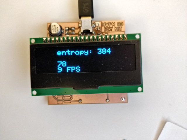
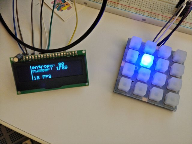
- Connect noise board to ADC and report output.
- Use Rhys Weatherley’s RNG libraries to pull noise from ADC noise source (.h, .cpp) and
timer jitter, and then allow random numbers to be generated by button press.
Time is hard. This is like EE51 all over again.
Subsequently
After deciding that this platform is reasonable and that the hardware plan is probably not crazy I went ahead and designed a final project board:
Using a separate board designed to provide only an ISP header, I loaded the LUFA CDC bootloader onto the AT90USB1286. This allows uploading of code over the USB cable with avrdude, after exporting the .hex file from the Arduino IDE. Since the Teensy++ 2.0 is based on the same MCU as our self-designed board, no changes to the core code are required.
The best part is that the software I wrote works as-is with only minor modifications (to respect that I moved the display off the I2C bus and instead connect to it through SPI).