Matt Groh
Electronics Design
Welcome to the how to design an electronic circuit that lights up when you click a button page? Given a schematic (the image below), I'll build an electronic circuit using Eagle electronic circuit board design software) and the milling machine to create the printed circuit board.
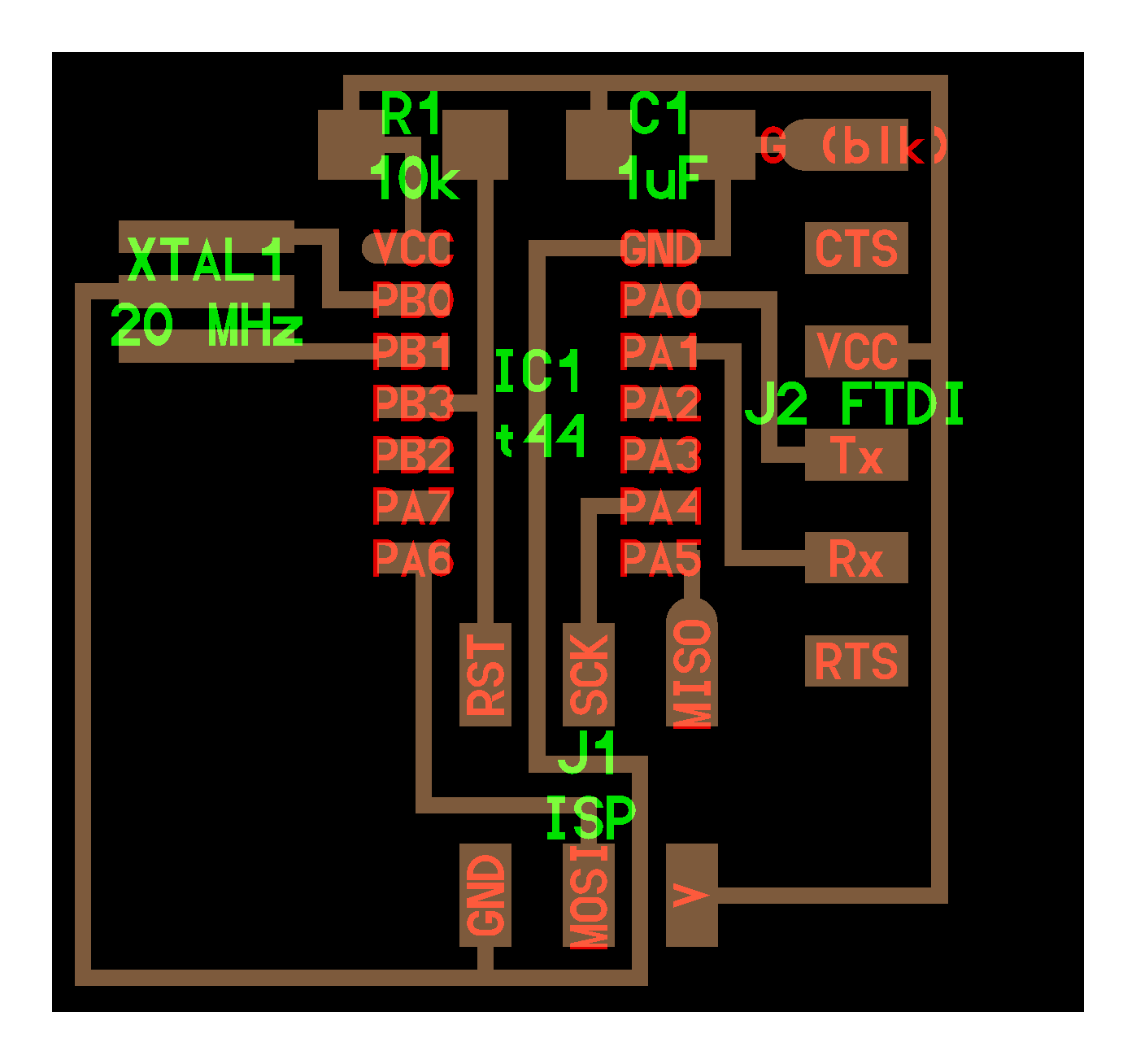
What we need to do is translate the components in the image (green labels) to the materials we have available and lay them out appropriately.
- XTAL1 20 MHz is a resonator, which is listed under RESONATOR
- R1 10k is a resistor, which is listed under RESISTOR1206
- C1 1uF is a capictor, which is listed under CAP1206.
- IC1 t44 is a microchip, which is listed under ATTINY44.
- J1 ISP is a microcontroller, which is listed under AVRISPSMD.
- J2 FTDI is a microcontroller, which is listed under FTDI-SMD-HEADER.
In addition to the materials in the image above, we need to add a button, a light, and a resistor (to avoid blowing up the light). It's probably a smart idea to add a third resistor between the switch and the ATTiny 44, but it's not necessary. You'll find these in Eagle by searching for a switch (go for the 6mm Switch) and an LED (searching for... LED) and a resistor (the RESISTOR1206).
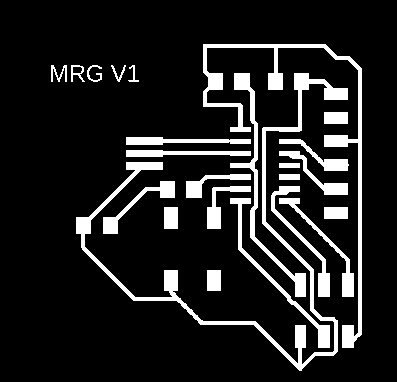
Here's what my ECB designs look like in schematic and board mode in the middle of the process
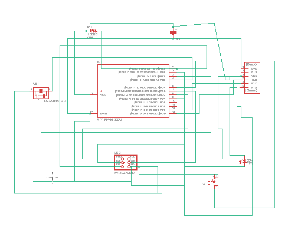
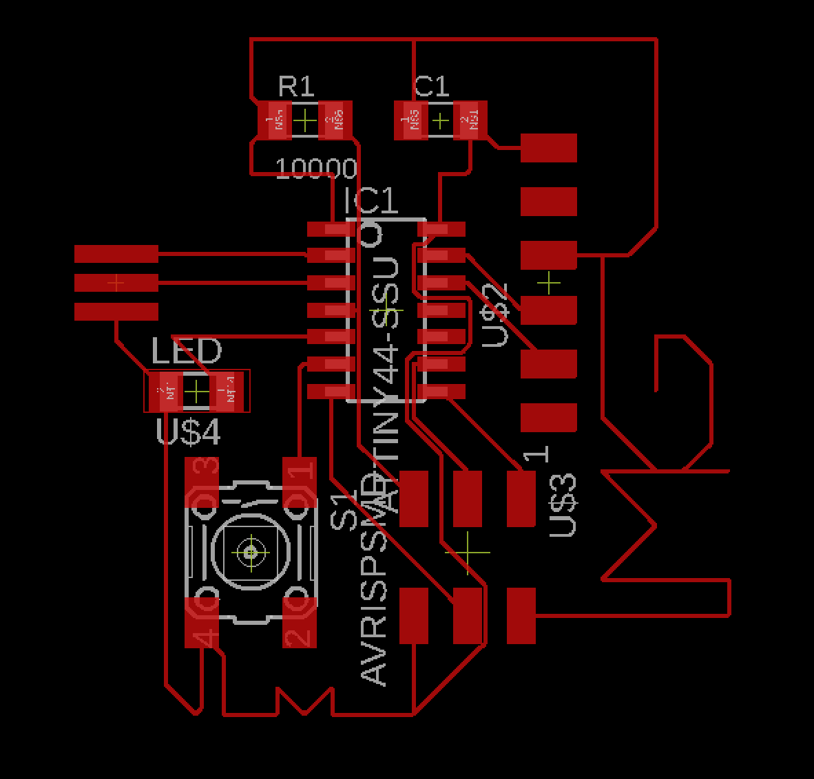
Since I don't want the LED to blow up, I added a resistor and I cleaned up the designs a bit to get these two layers that I'm sending to the milling machine.
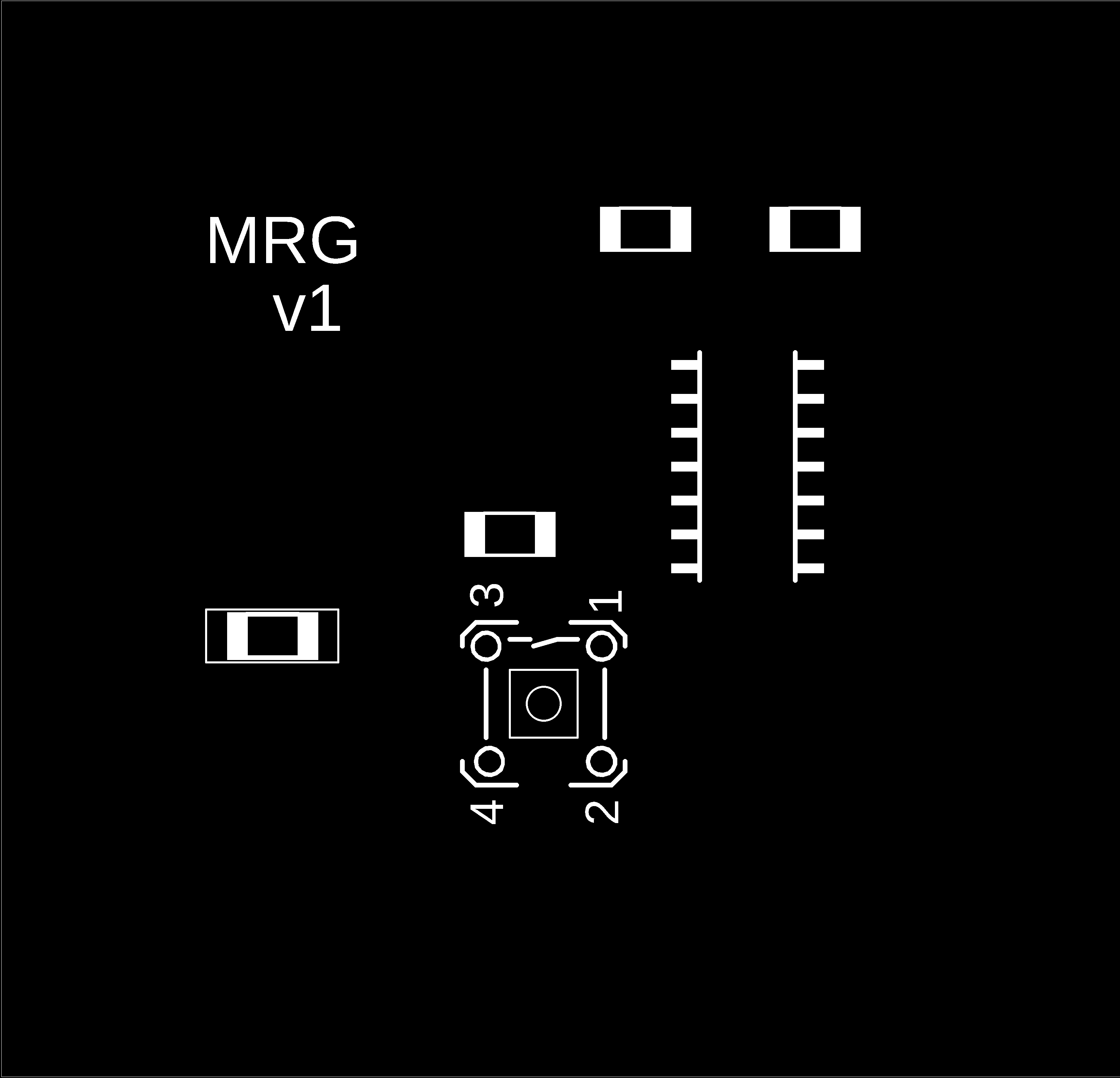
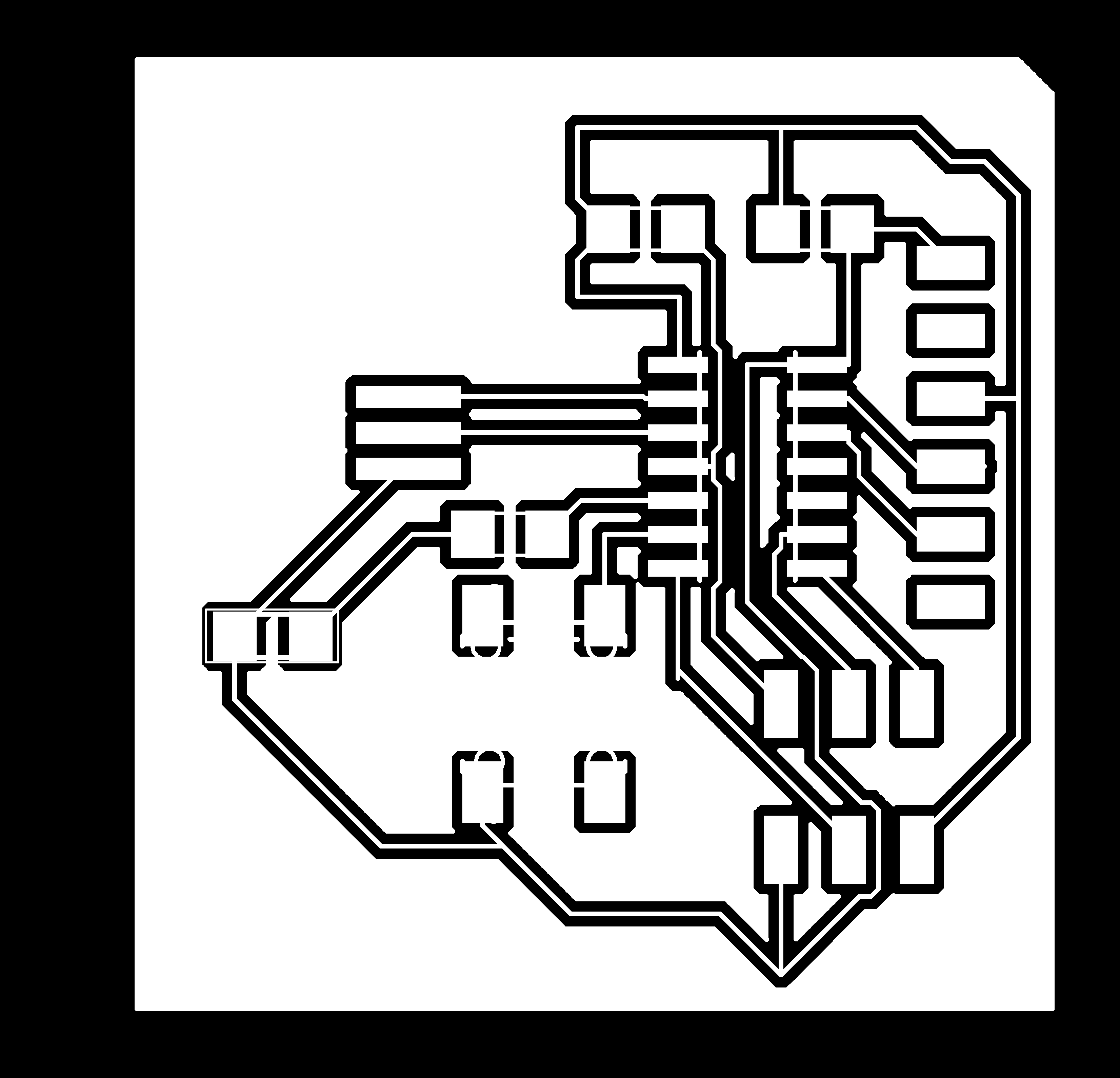
Wait a second! Those designs are off! Whast I need is the cut pattern for the 1/32 inch endmill head and the cut pattern for the 1/64 inch endlmill head. You can get these by typing `disp none top` and `disp none dim` into the command prompt. And, there's another thing. It's important to save these files as 1000 DPI in monochrome. And! This is absurd, but it's a thing with this particular set up: you need to open the saved images in an editor (like Photoshop) and reduce the height/width by half to be the right number of pixels for the electronic components and the milling machine. Here are the correct designs.

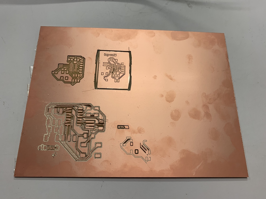
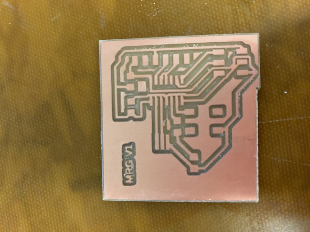
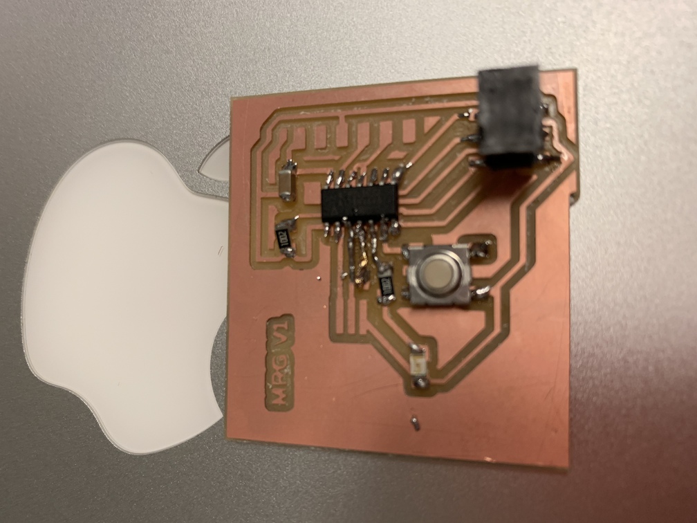
And here goes the milling. The three images below show (1) the first version when I didn't reduce the height/width by half, which was too big (2) the PCB without components (3) the PCB with most of the components. The FTDI headers were unavailable on Sunday. Along the way, I broke two of the mill heads. I broke a 1/32 and a 1/64. Oopsies! The 1/64 mill head broke because the copper material was not perfectly flat and the minor elevation difference across the board created a problem. The 1/32 mill head broke because I was debugging the MODs server because the mill was not cutting deeply enough. I kept trying to change the cut depth and max cut depth, which are the appropriate things to do. But the mill didn't seem to respond over many attemps. So, I tried to change another parameter, which was the Z resting height. I changed that to 0... which meant that when the mill went into view mode it scraped the head against the board and bend the mill head. Well, random search on a software interface connected to a hardware interface will lead to results like these.
By Tuesday night, it got way too busy. So, there's still some work to be done