Matt Groh
Coup D'oeil Cravate
Inspiration
Sometimes what you're looking for is right in front of you. The Coup D'oeil Cravate concept is a tie with LEDs stiched inside, which are programmed to produce a hidden message through a Saccade-based display. This idea springs from the Missing Objects aesthetics of absence and conversations with Joost Bonsen. Here's a video showing a Saccade-based display.
And here's the boss wearing a bolo tie. The big idea is a Saccade-display bolo tie. But, we'll go for the standard tie to start. And, we'll make this project tractable and de-risk the binary nature of electronics components through a spiral development process starting with something small and relatively easy and incrementally increasing the complexity.

Charlieplexing
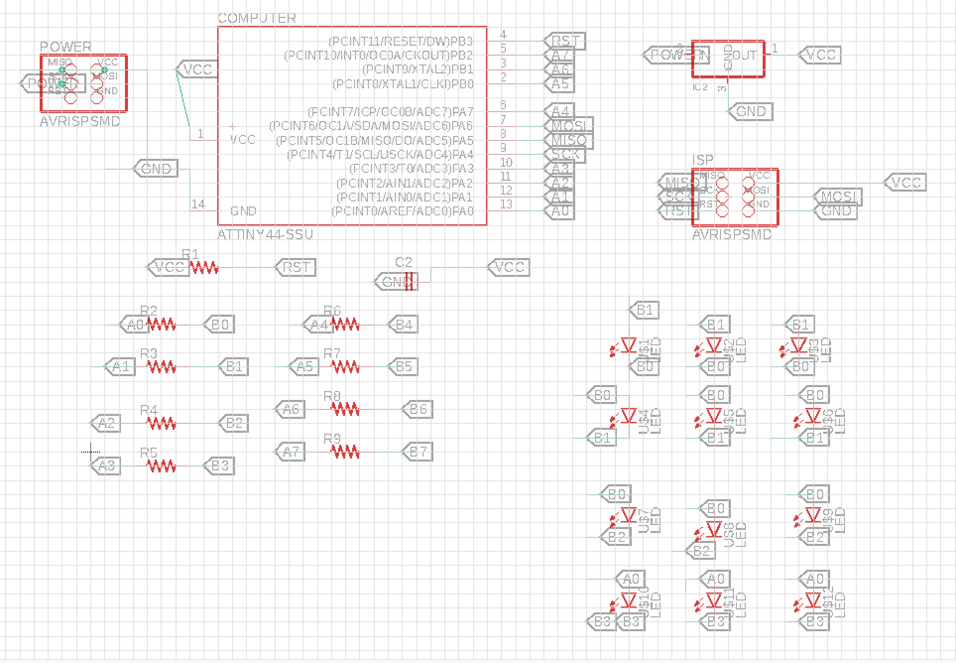
Charlieplexing is a technique for driving a multiplexed display with relatively few pins. For the purposes of the Coup D'oeil Cravate How to Make project, Charlieplexing allows us to control lots of LEDs with minimal microcontroller pins. Specifically, \(n\) pins can drive \(n(n-1)\) LEDs. I will be using the ATTiny44 microcontroller, which has 14 pins with 9 available for LEDs once the other 5 have been routed to the power and ISP programmer. With 9 available pins on the ATTiny44 , we can drive up to 72 LEDs. As an intermediary goal for the final project, I'll drive 20 LEDs with 5 pins.
Electronics
Step 1: Designing a Double-Sided One Dimensional Charlieplexed Circuit Board
Isaac Newton once wrote, "If I have seen further it is by standing on the shoulders of giants." My design starts with Neil's charlieplexing example from the output devices week.
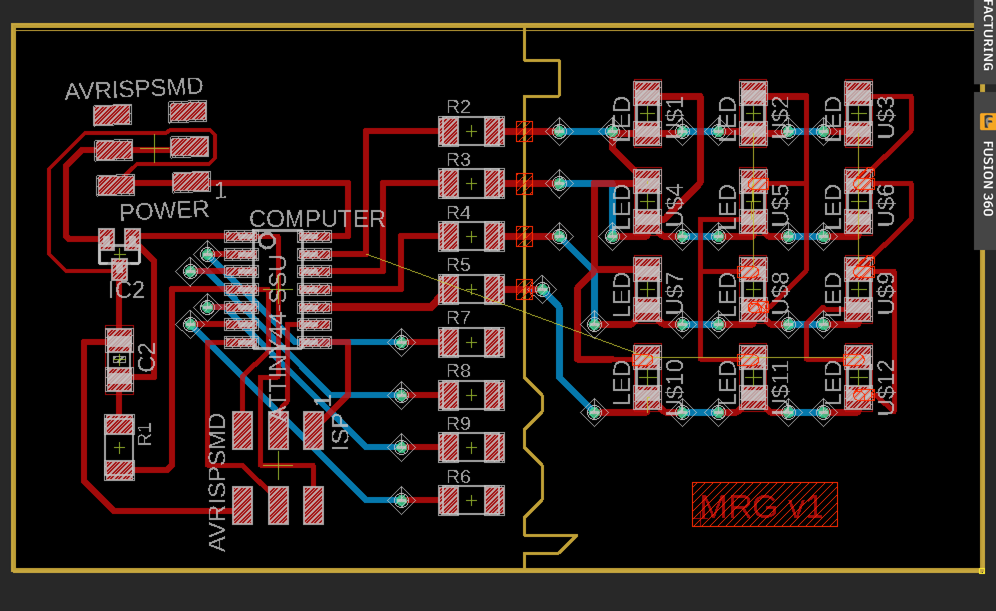
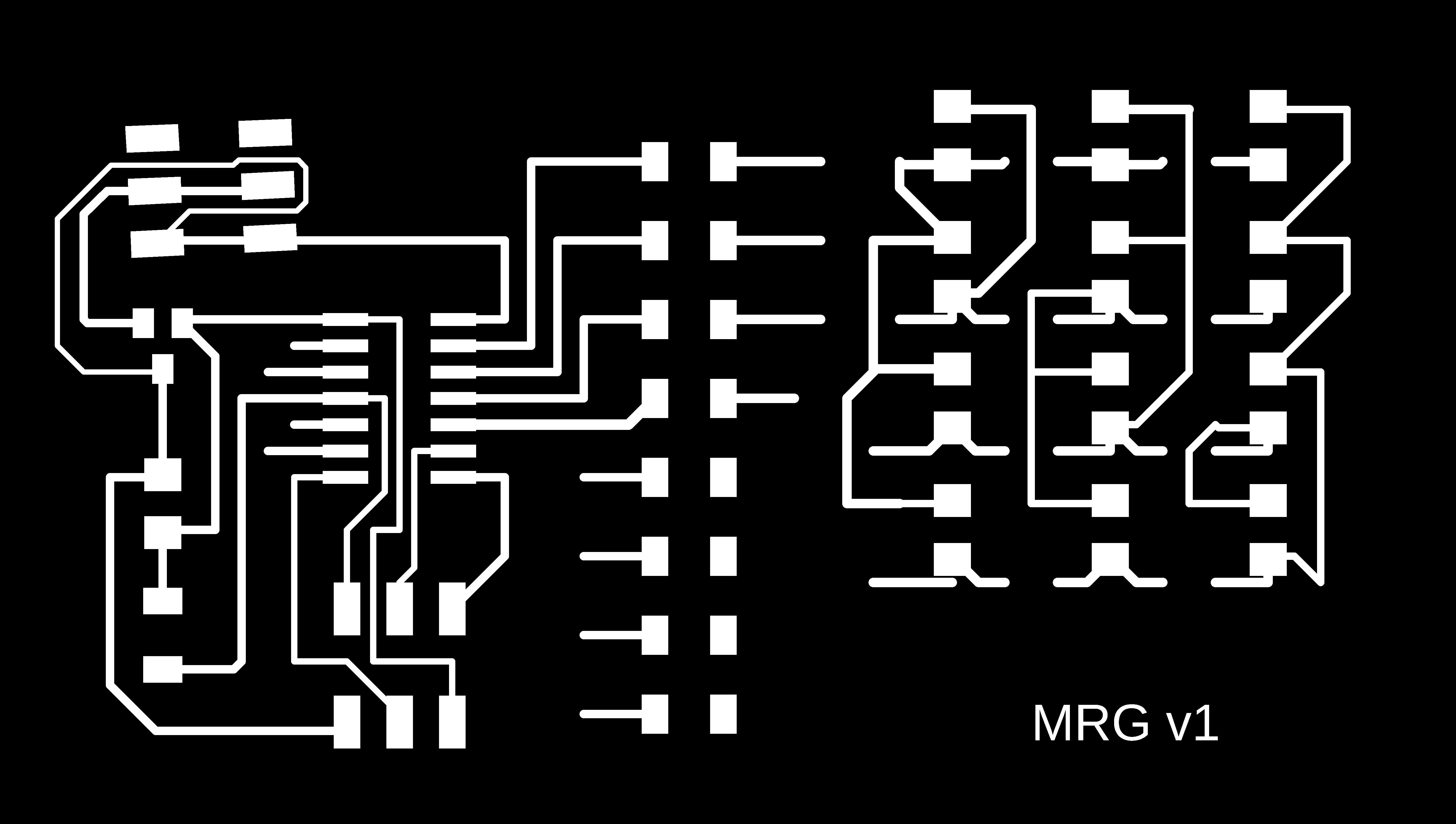
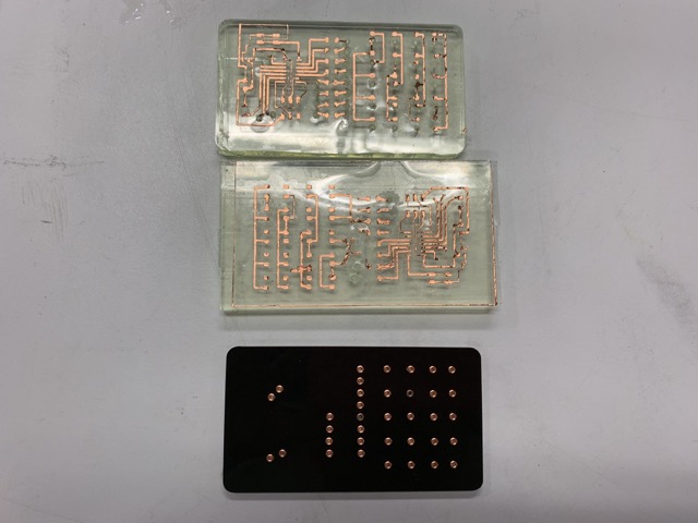
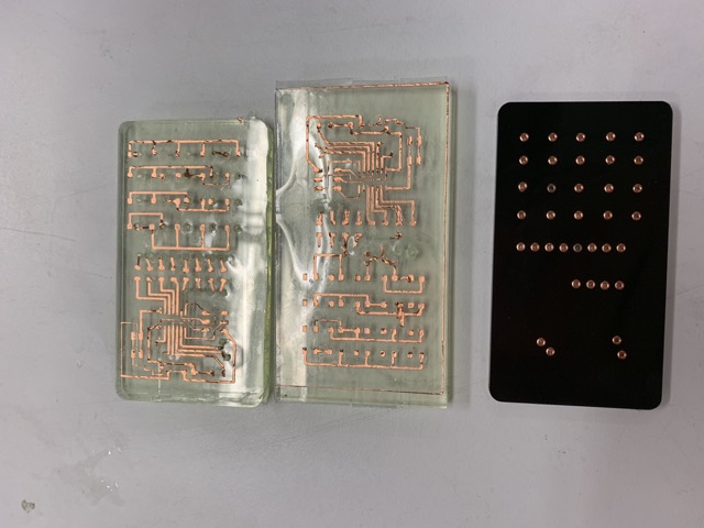
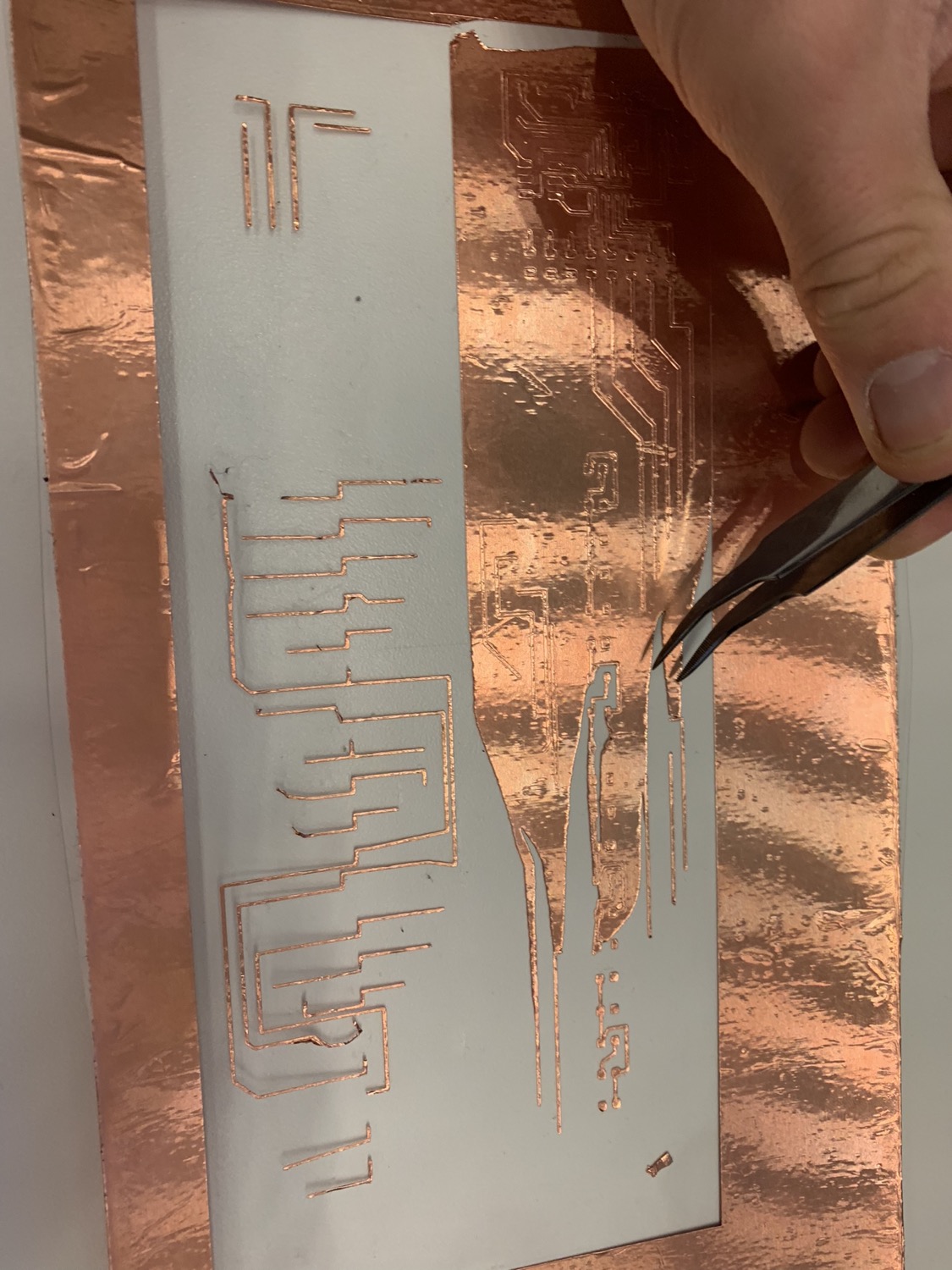
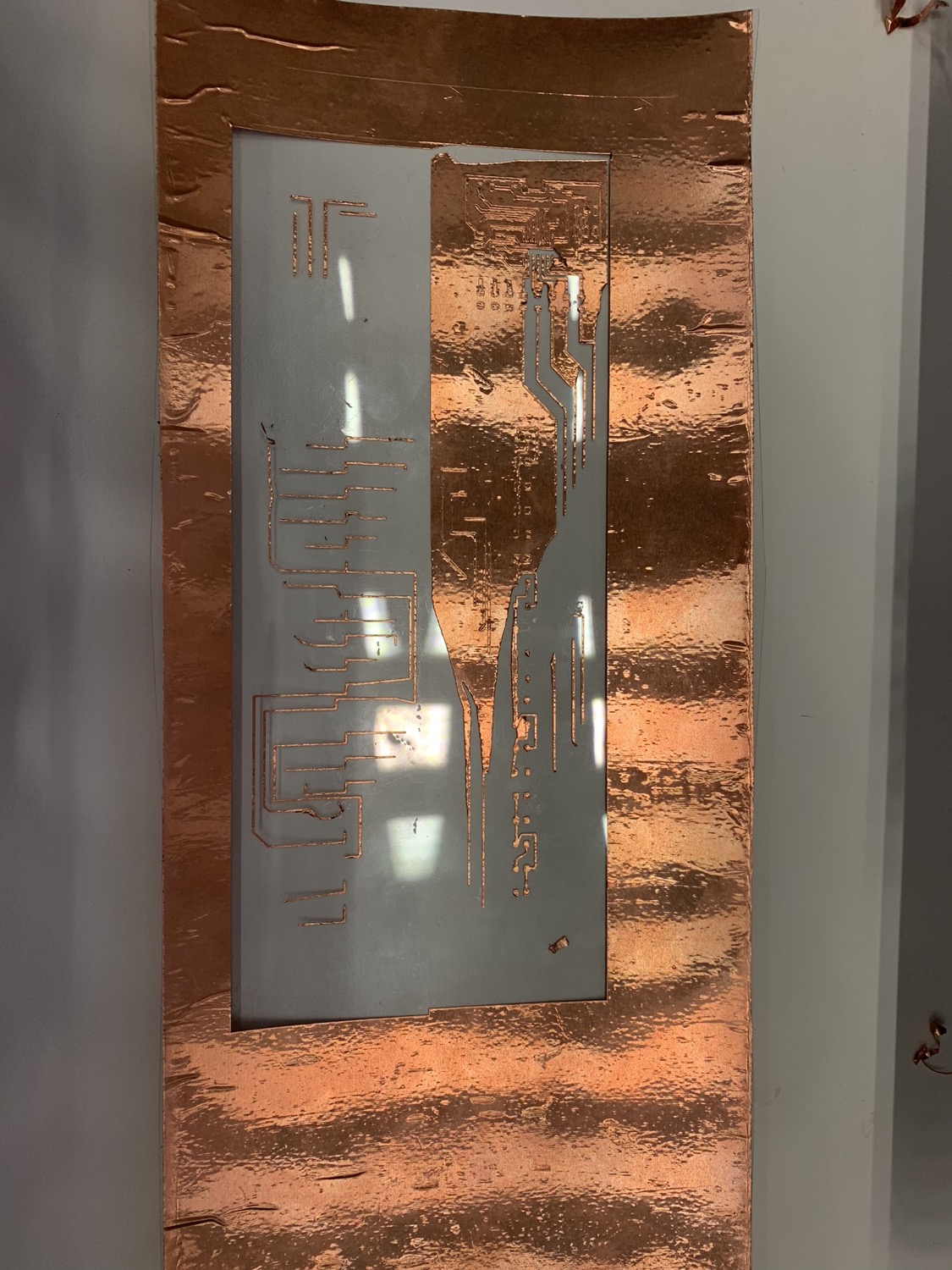
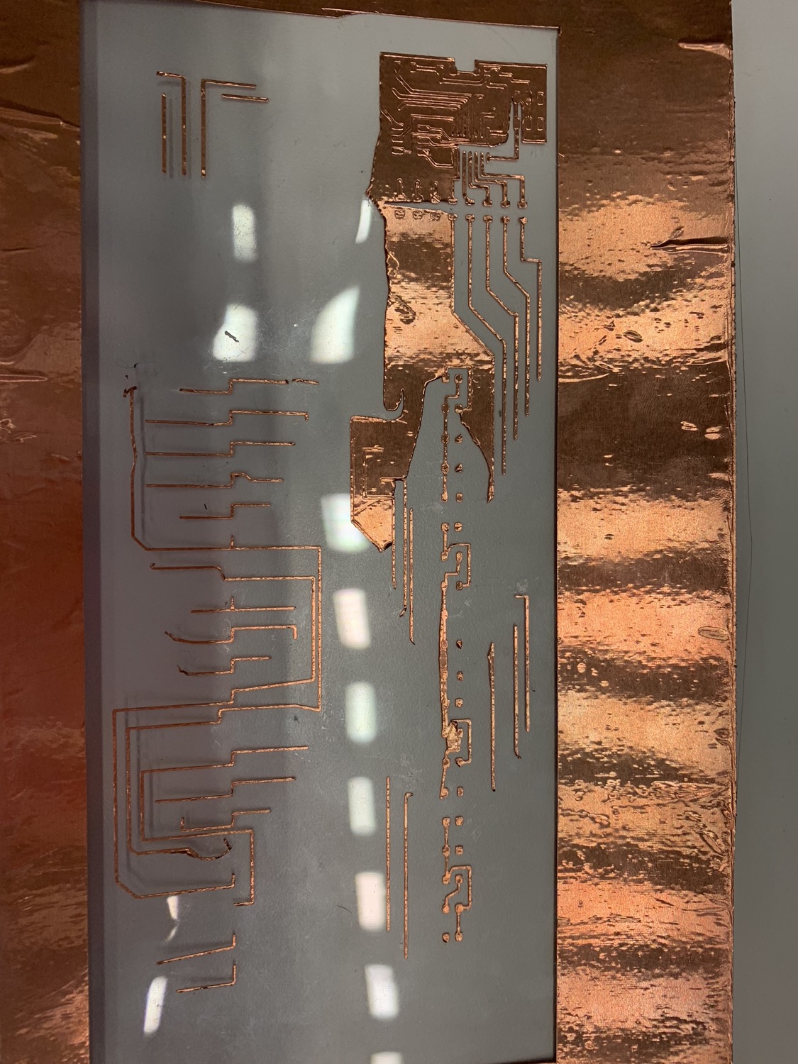
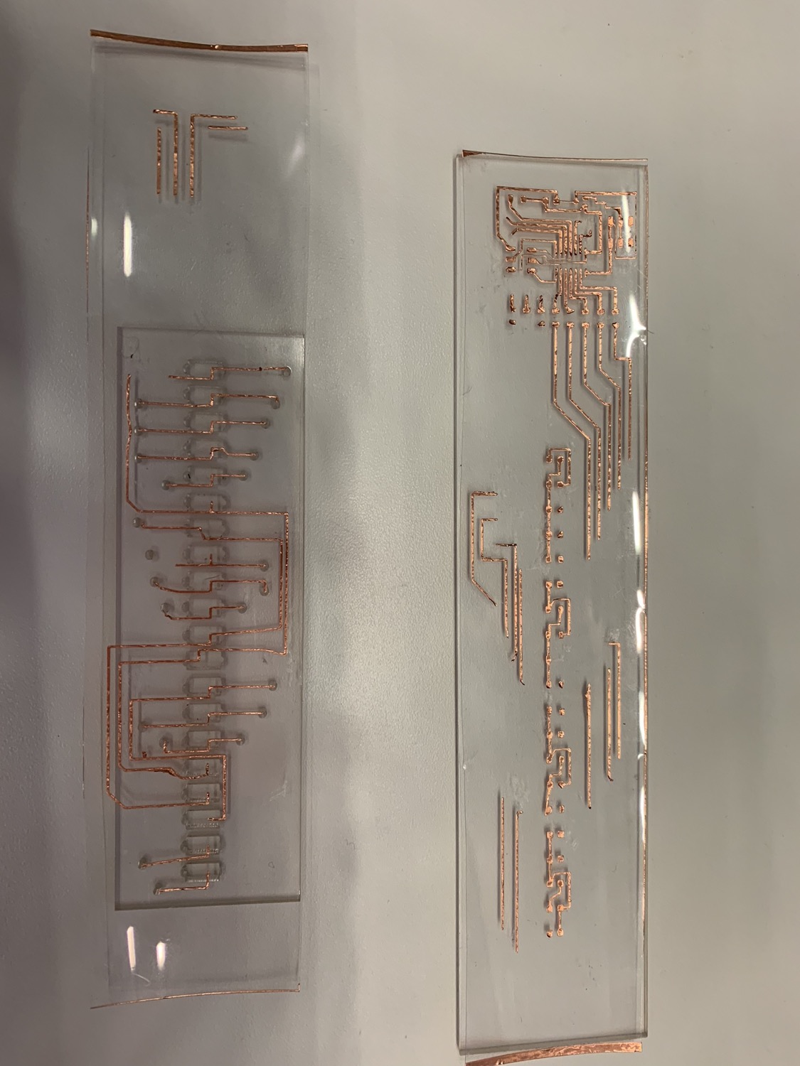
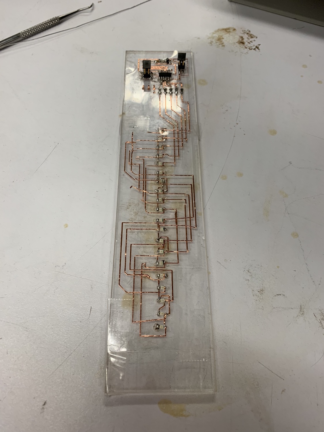
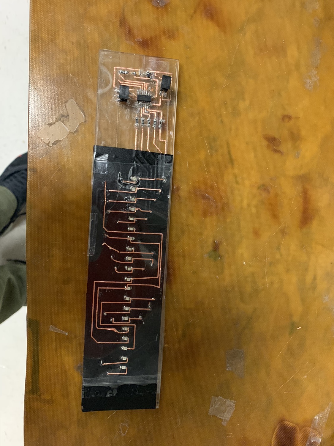
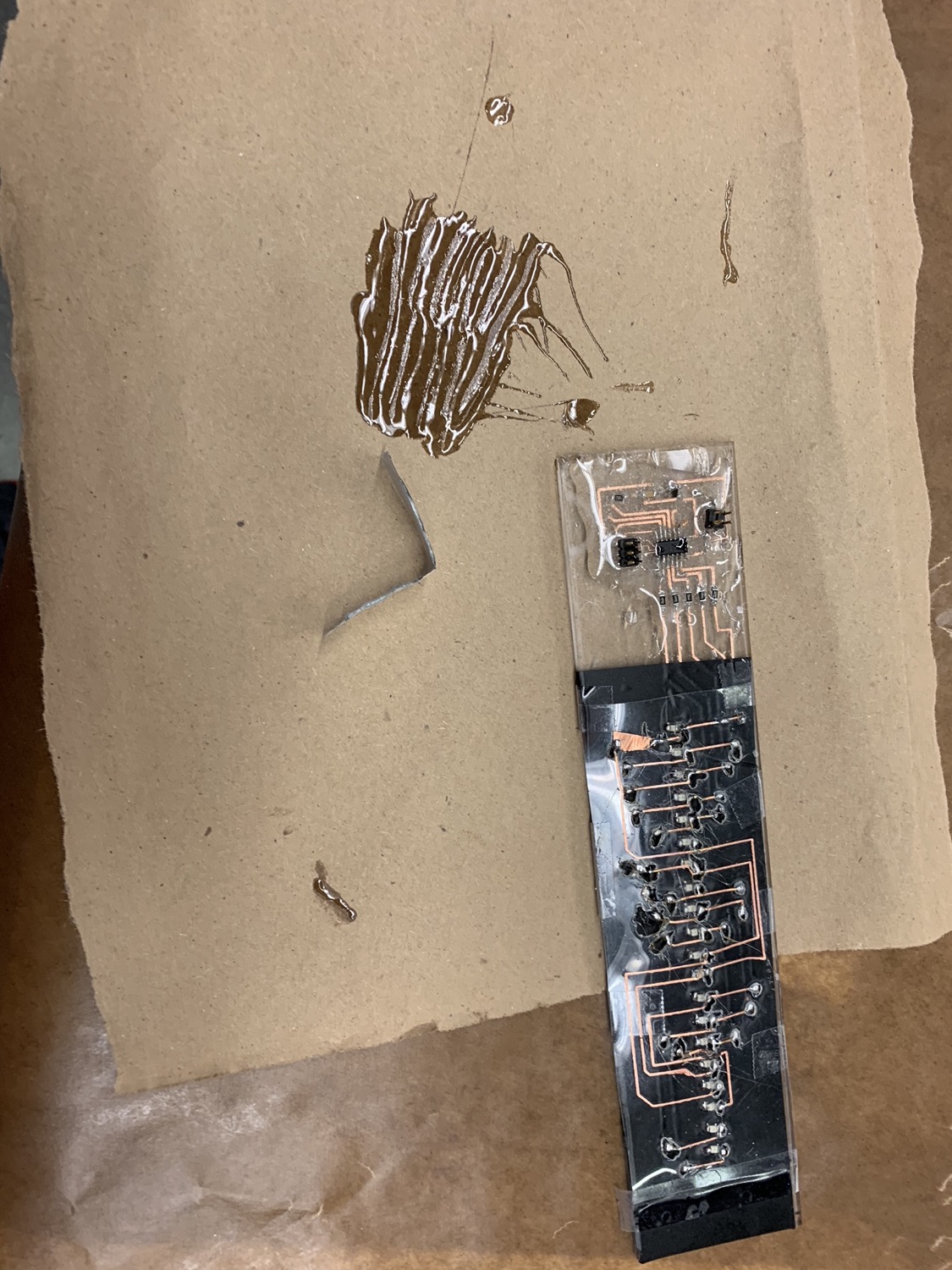
I rearranged the 2d array of LEDs into a single 1d array. I also added copper traces from the rest of the pins to vias and additional resistors that would enable the next development cycle with additional LEDs. Otherwise, I kept the board design the same. Here's a picture of the bottom of the board.
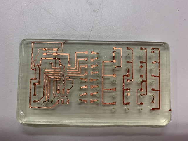
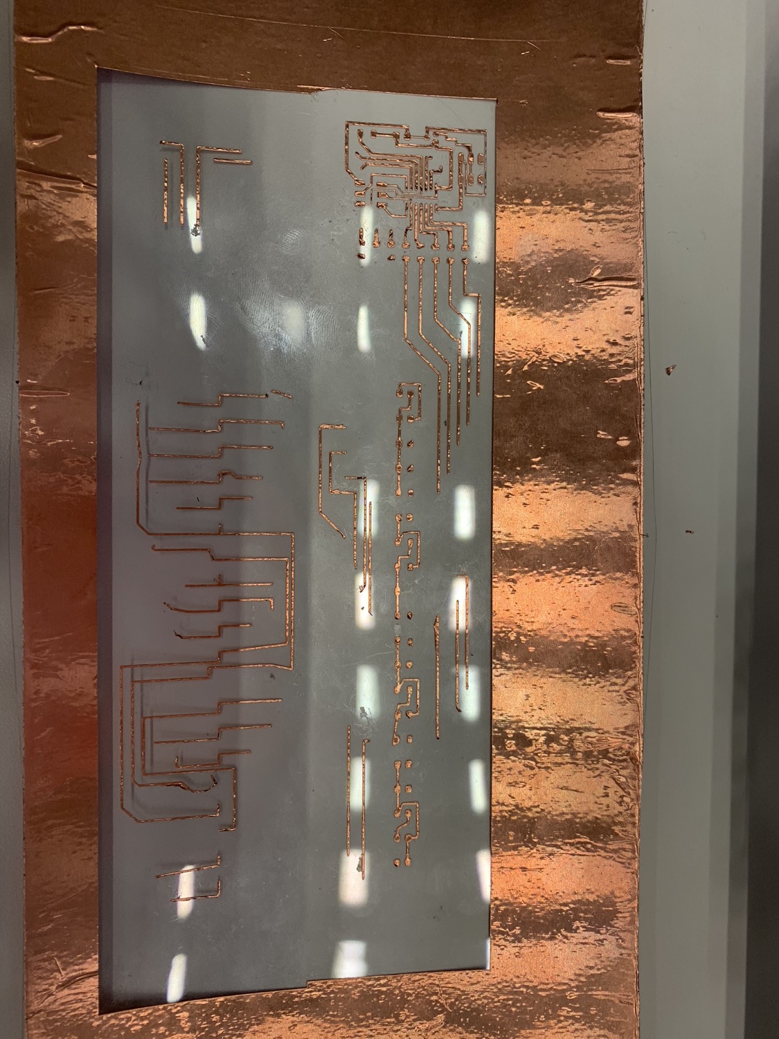
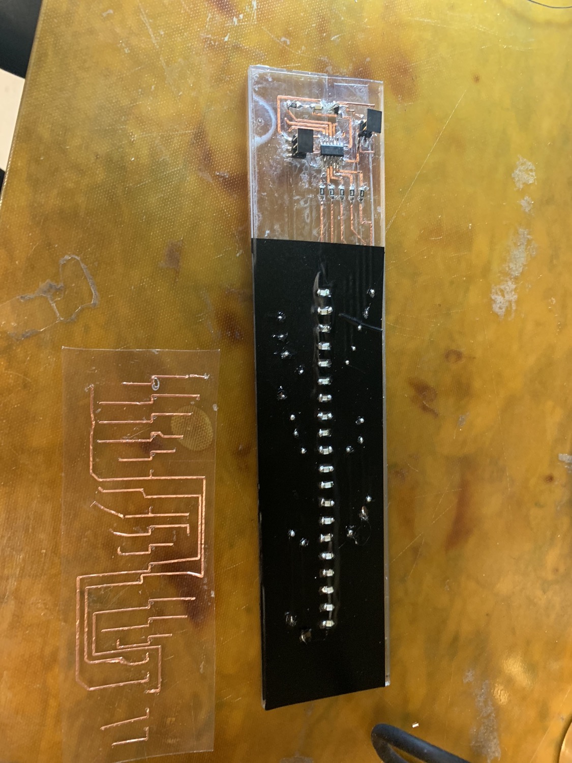
And here's a picture of the top of the board. The traces on the left would technically be below the previous image, but I ended up not using them because I only used 5 pins.

My goal would be to build a flexible circuit board, but this development cycle I wanted to mount the circuit on an acrylic block to make it more sturdy. The larger rectangle is the backing for the circuit and the rectangle with holes is meant to be the top layer. The acrylic turned out to be too thick for the vias in the workshop, so I ditched the holy rectangle. The .pdf below is the cut file for the acrylic on the laser cutter.
Here's the cut file for the copper on acetate.
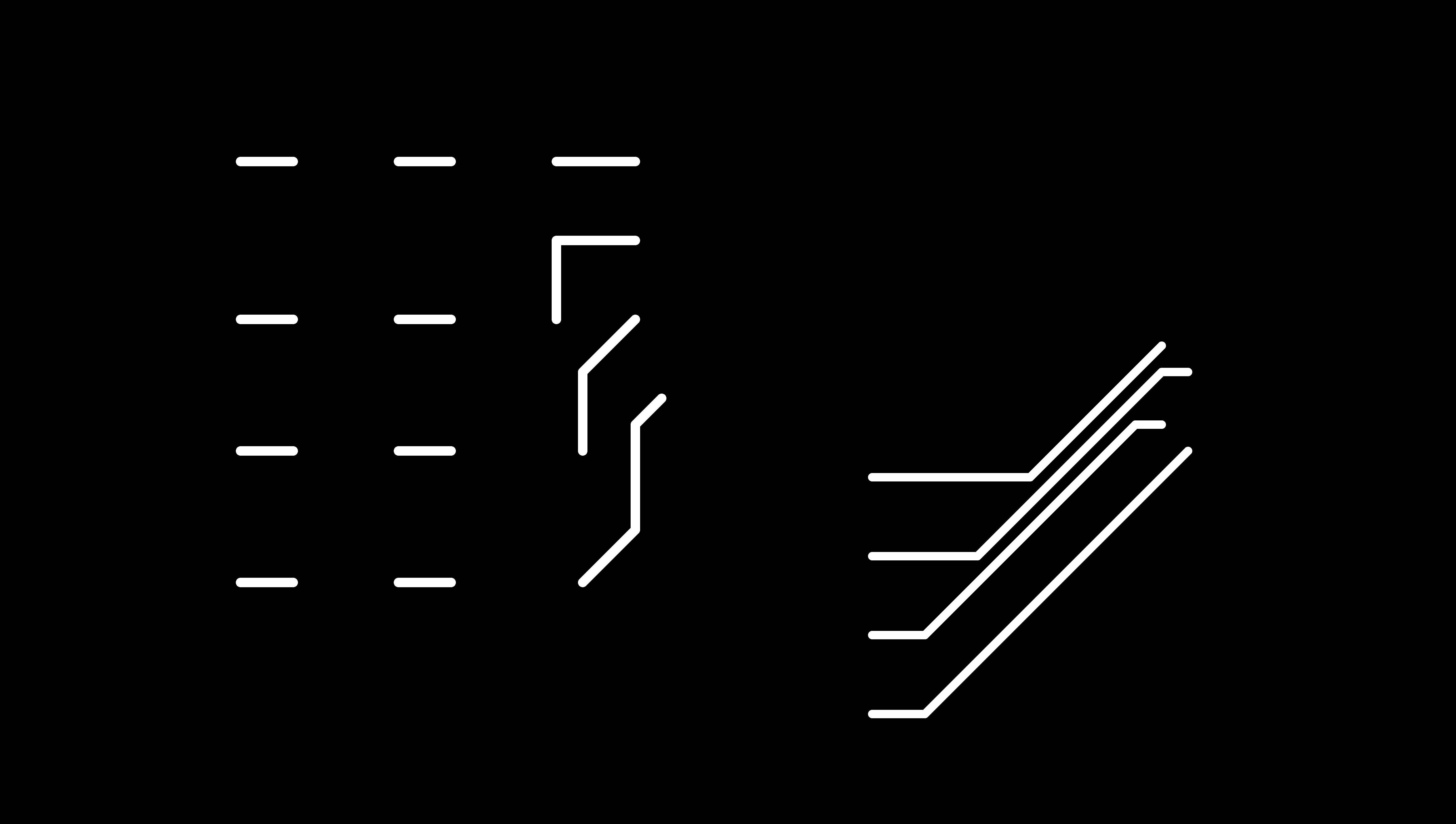
And, here's the cut file for the vinyl, which goes on top of the bottom layer to prevent the bottom traces from touching the top traces.
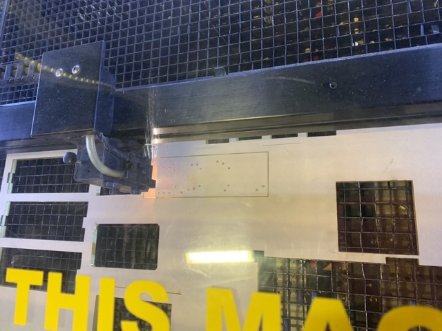
Step 2: Laser Cutting and Vinyl Cutting
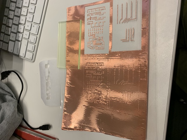
The key to the laser cutter is focus and air and a little bit of design. Save you design files as a .pdf and open them up on Corel Draw. Then, you'll want to set the Corel Draw program to the dimensions of the laser cutter. You'll need to focus the laser (this is essentially zero-ing the z-axis), and you can start printing. I printed on acrylic, and I chose the following settings: 100 power (that's the max) and 1.6 speed (that's nearly the slowest). Also, make sure to check the box that says air, which will circulate the air and avoid flames. Here's a pic and a video of the laser cutter in prcoess.
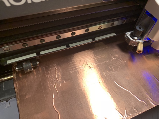
The trick to the vinyl cutter is material and sharpness. On the sharpness side, you just want to make sure the blade doesn't have gunk on it. On the material side, it's about your inputs. When I put copper on vinyl, I could never get cuts that didn't mess up the copper traces. When I put copper on acetate, it just worked. The settings that I used were 80 for force and 20 for speed. These same setting work when just cutting vinyl.
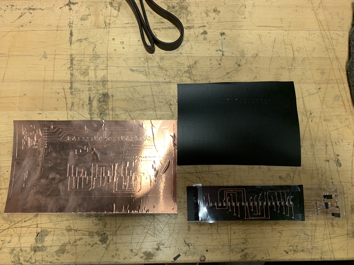
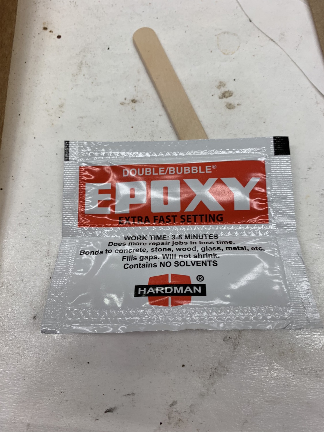
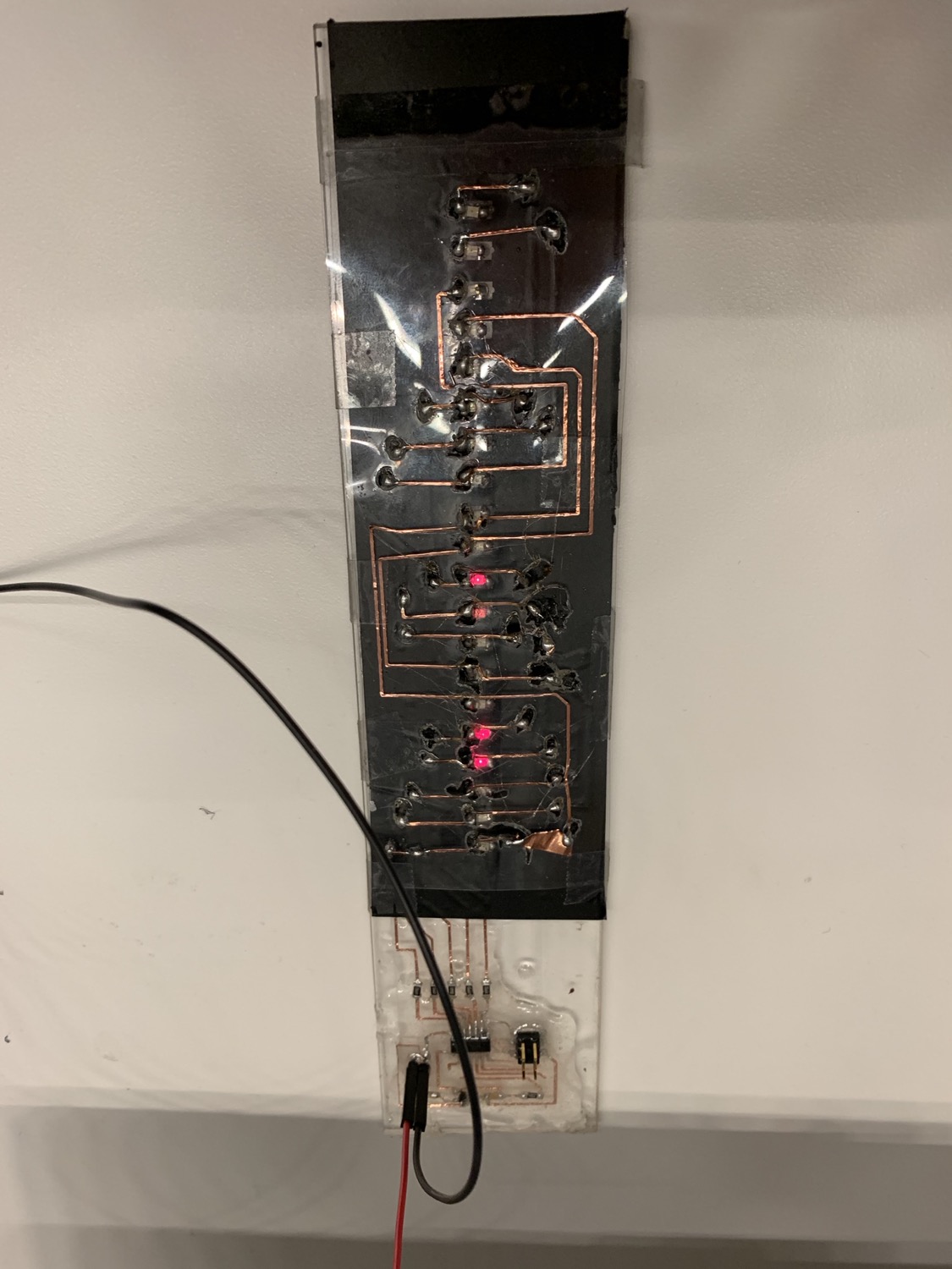
Step 3: Copper on Acetate on Vinyl on Copper on Acetate on Acrylic with lots of Solder and Epoxy
Step 4: Programming the LED Array
In order to program the LED array, you'll want to connect a programmer like the AVRISP-2 to the ISP and an FTDI header to the ground and VCC pins of the power component. Note: the programmer will fail if the board is not powered.
mkdir code && cd code
curl http://academy.cba.mit.edu/classes/output_devices/array/hello.array.44.2.c > hello.array.44.2.c
curl http://academy.cba.mit.edu/classes/output_devices/array/hello.array.44.2.make > makefile
make
make program-avrisp2
Then, if it programs correctly, you should see:
avr-objcopy -O ihex hello.array.44.2.out hello.array.44.2.c.hex;\
    avr-size --mcu=attiny44 --format=avr hello.array.44.2.out
AVR Memory Usage
----------------
Device: attiny44

Program:     366 bytes (8.9% Full)
(.text + .data + .bootloader)

Data:          1 bytes (0.4% Full)
(.data + .bss + .noinit)


avrdude -p t44 -P usb -c avrisp2 -U flash:w:hello.array.44.2.c.hex

avrdude: AVR device initialized and ready to accept instructions

Reading | ################################################## | 100% 0.00s

avrdude: Device signature = 0x1e9207 (probably t44)
avrdude: NOTE: "flash" memory has been specified, an erase cycle will be performed
         To disable this feature, specify the -D option.
avrdude: erasing chip
avrdude: reading input file "hello.array.44.2.c.hex"
avrdude: input file hello.array.44.2.c.hex auto detected as Intel Hex
avrdude: writing flash (366 bytes):

Writing | ################################################## | 100% 0.16s

avrdude: 366 bytes of flash written
avrdude: verifying flash memory against hello.array.44.2.c.hex:
avrdude: load data flash data from input file hello.array.44.2.c.hex:
avrdude: input file hello.array.44.2.c.hex auto detected as Intel Hex
avrdude: input file hello.array.44.2.c.hex contains 366 bytes
avrdude: reading on-chip flash data:

Reading | ################################################## | 100% 0.16s

avrdude: verifying ...
avrdude: 366 bytes of flash verified

avrdude: safemode: Fuses OK (E:FF, H:DF, L:62)

avrdude done. Thank you. 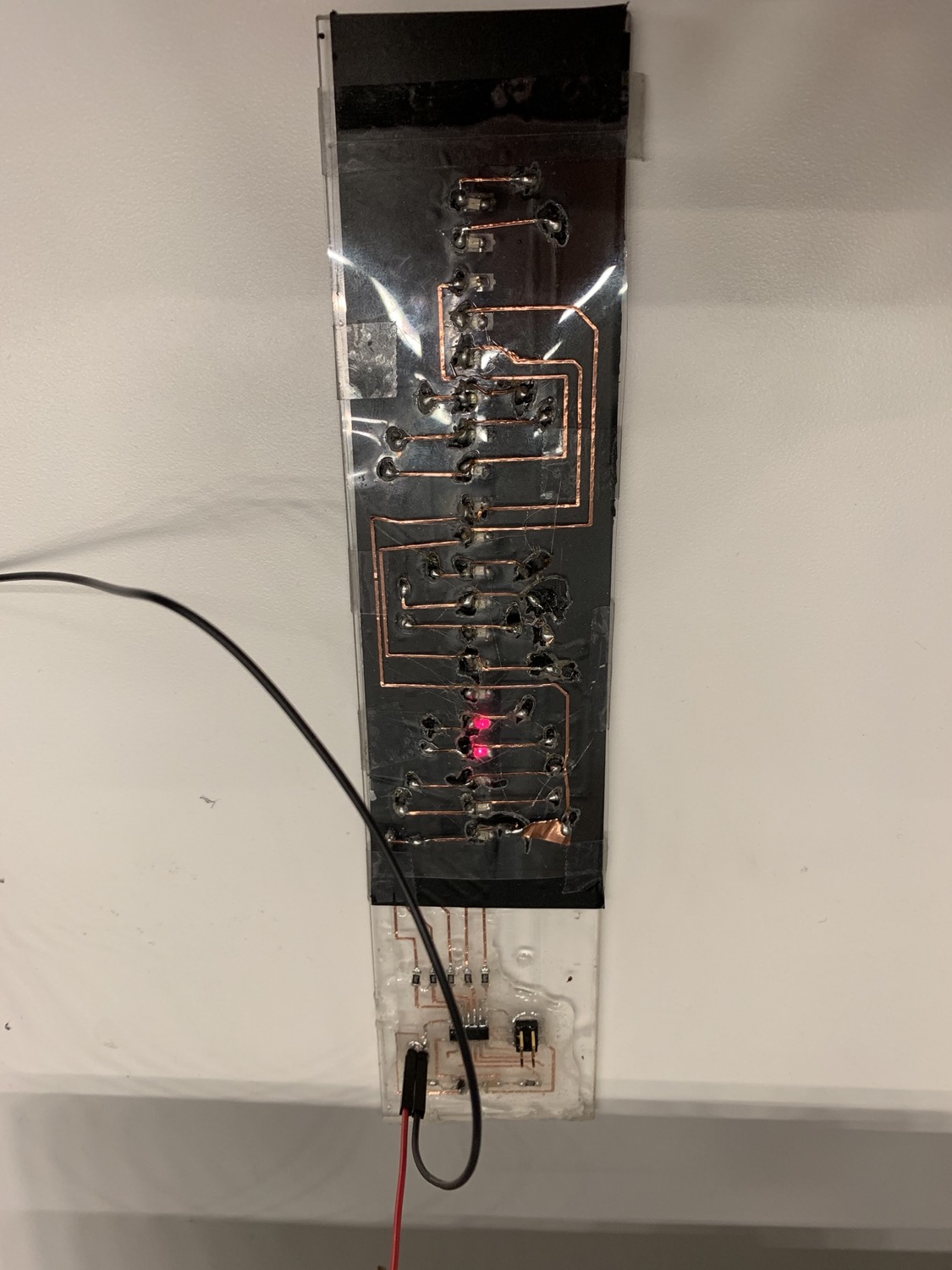
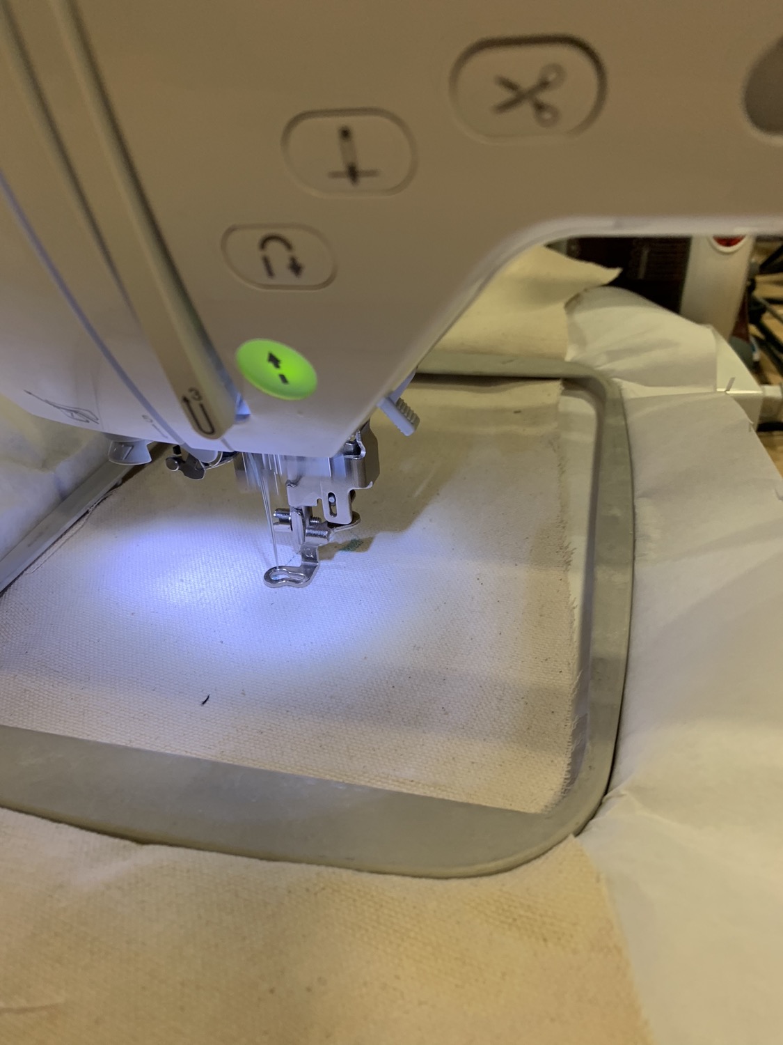
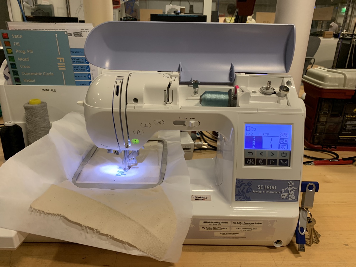
Step 5: Embroidery and Sewing
The final step is sewing a tie together and embroidering the Miss.o logo.

The "Brother" sewing machine has a software design cool called PE Design Center. Tom Lutz wrote an awesome how-to on using the embroidery software, which I followed to produce this .ps file to plug into the "Brother." Then, it's just setting up the sewing machine and having a go.
Voila
The Process
It appears that I boiled this Coupe D'oeil Cravate project down to 5 steps. Admittedly, the design and building process were less linear and more chaotic. One of my favorite artists, Mari Andrew, visualizes this process perfectly.
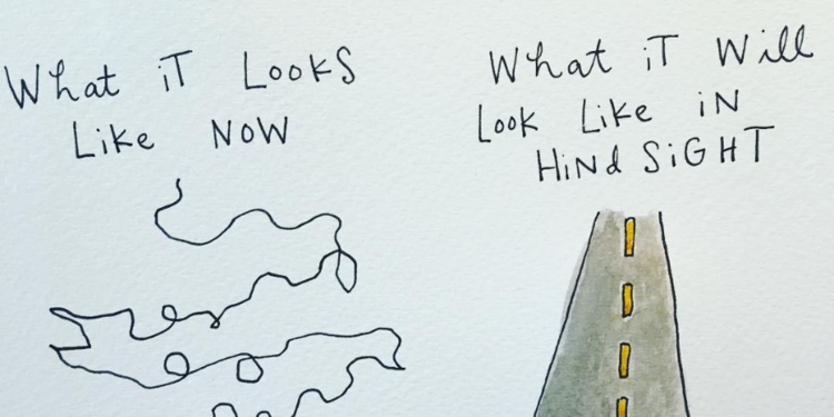
Of course, you're reading this with my hindsight vision. Trust me. What it looked like while I was building this is the squiggle on the left. Pretty neat how a project can be a microcosm of life!
Here's a small gallery of images showing designs and attempts along the way. Also, we're supposed to say the cost of materials. The only thing I purchases was a black tie for $10 that I ended up not using.