Matt Groh
Output Devices
This week I'll walk through how to make a motor spin the way you want it to spin. We start off with a servo motor schematic, which you can can see below. And, we'll add a button.
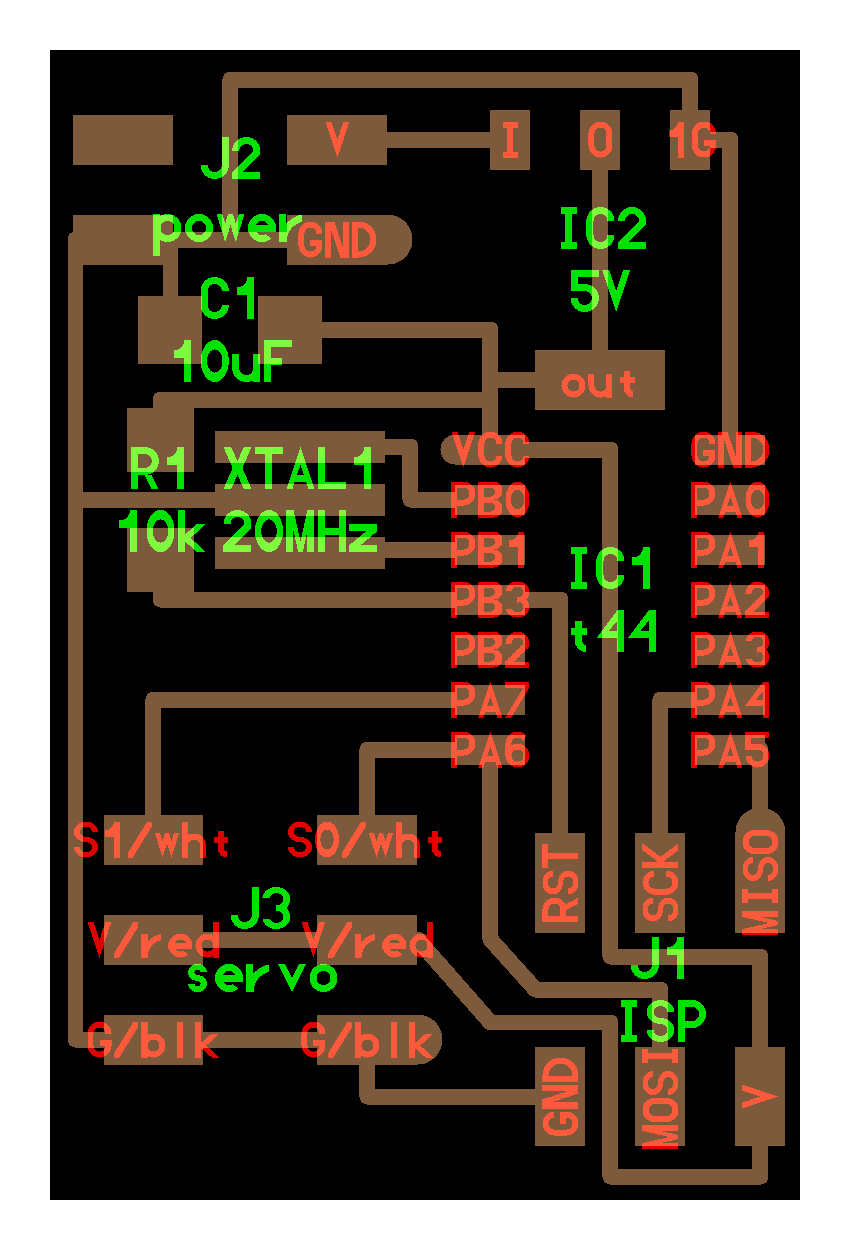


What we need to do is translate the components in the image (green labels) to the materials we have available and lay them out appropriately. Here's a translation from the green labels to the names of the components in Eagle. You have to read the datasheets to figure out this translation.
- IC1 t44 is a microchip, which is listed under ATTINY44.
- IC2 5V is a microchip, which is listed under REGULATOR_SOT223.
- XTAL1 20 MHz is a resonator, which is listed under RESONATOR
- R1 10k is a resistor, which is listed under RESISTOR1206
- C1 22uF is a capictor, which is listed under CAP1206. This circuit calls for 22 uF. If you don't have a 22 uF capacitor, you can stack smalled ones vertically to do the trick.
- J1 ISP is a microcontroller, which is listed under AVRISPSMD.
- J2 power is a microcontroller, which is listed under ?. It's not listed and my hack is to substitute with the AVRISPSMD
- J3 servo is a motor, which is listed under ?. It's not listed and my hack is to substitute with the AVRISPSMD
- And, we'll add in a button too: 6MM_SWITCH
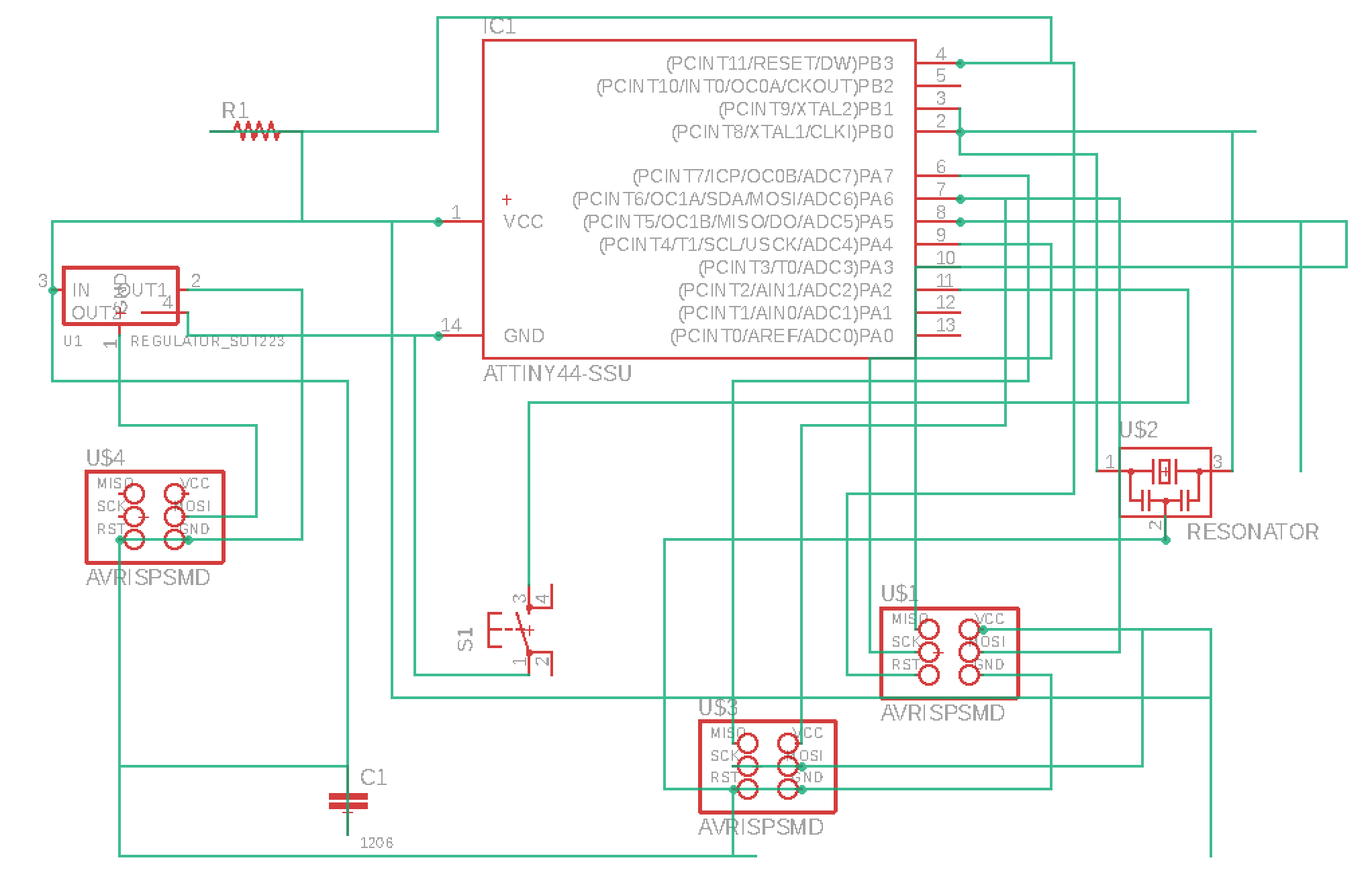
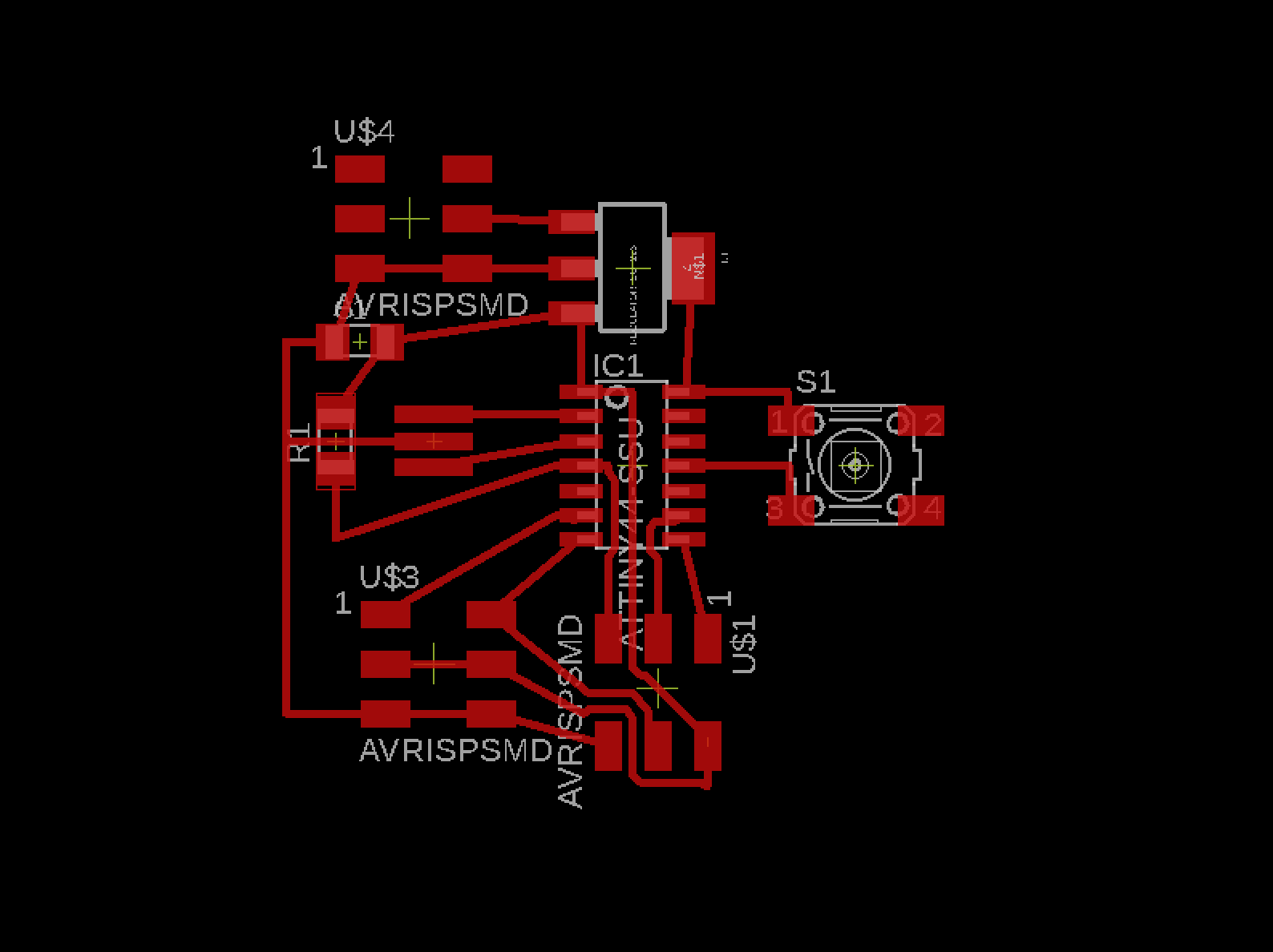
With Eagle, we can design the schematic with all the components, approrpriately place the copper traces on the board, and create a traces and cutout files for creating the physical board.
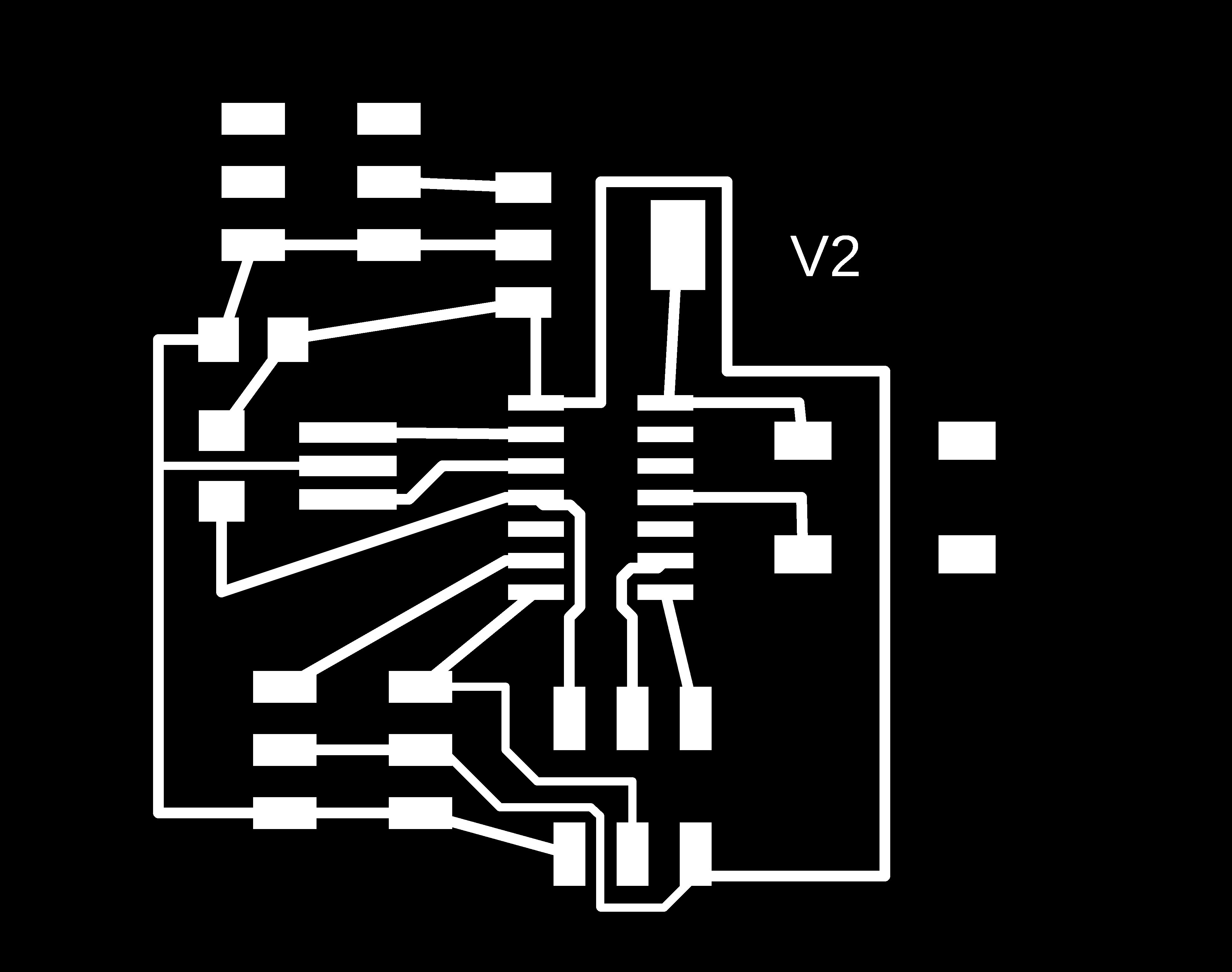

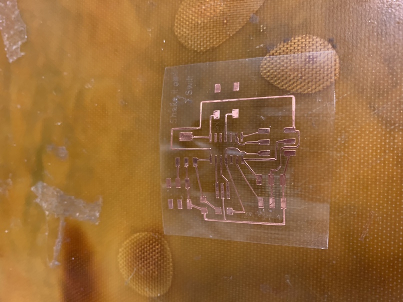
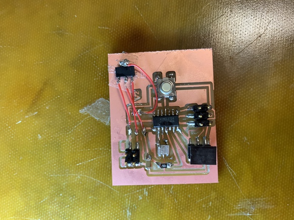
With the traces and outlines, it's time to go IRL and cut this circuit. This week wasn't as smooth as last week. Ocean walked me through vinyl cutting the circuit, and I was able to produce a beautiful board. One issue is the copper wires look quite thin. unfortunately, after I soldered everything on I got the standard r=-1 error, which means I couldn't load the code onto the device. One of the issues I had with soldering on copper adhered to acetate was the copper sometimes lost its stickiness and moved while I was soldering.
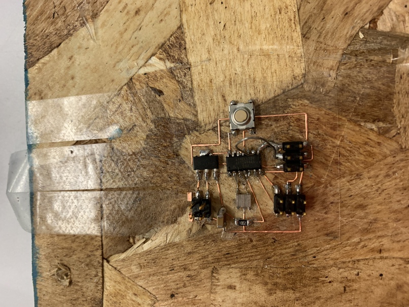
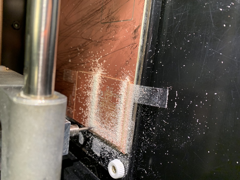
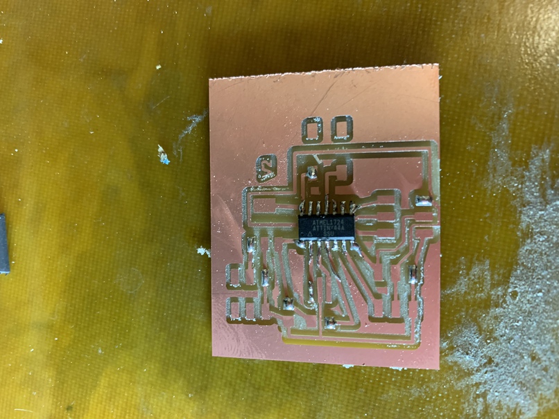
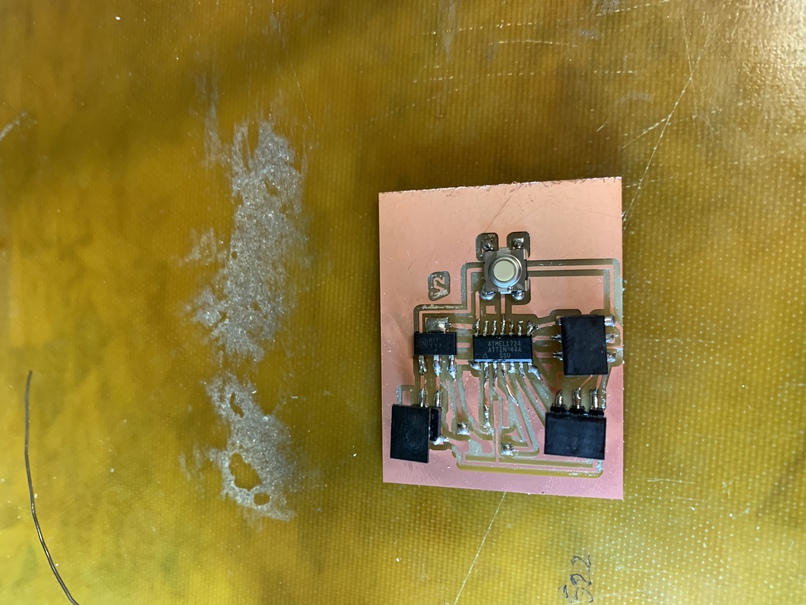
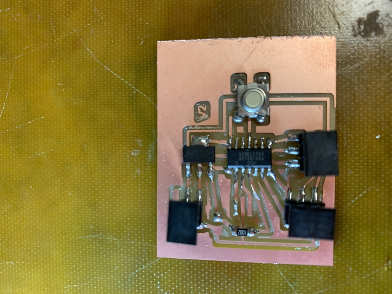
So, now it's back to the milling machine. Here's what it looks like
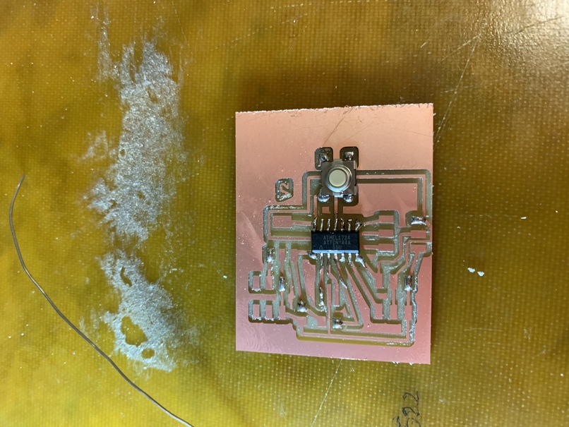
And, I got another r=-1 error when trying to load the code onto the circuit. So, I came to office hours and chatted with Brian. After quite a long time debugging, we (and first Brian) realized that the data sheet of the regulator does not match the regulator in the schema provided online. And after adjusting, we realized (and first Brian) that the fat side of the regulator is the same as the middle pin (not ground). This required jumper wires and lots of patience debugging. I wouldn't have completed the assignment this week without Brian's help! So, thank you Brian.
Brian is awesome!
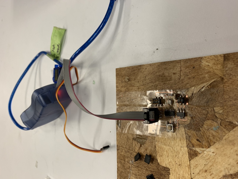
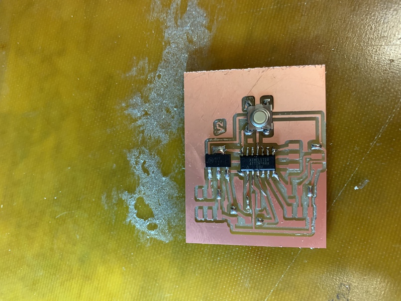
This is an image of the initial jumper wires. This had to be re-jumped again because the fat side isn't ground.
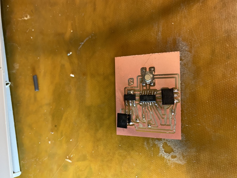
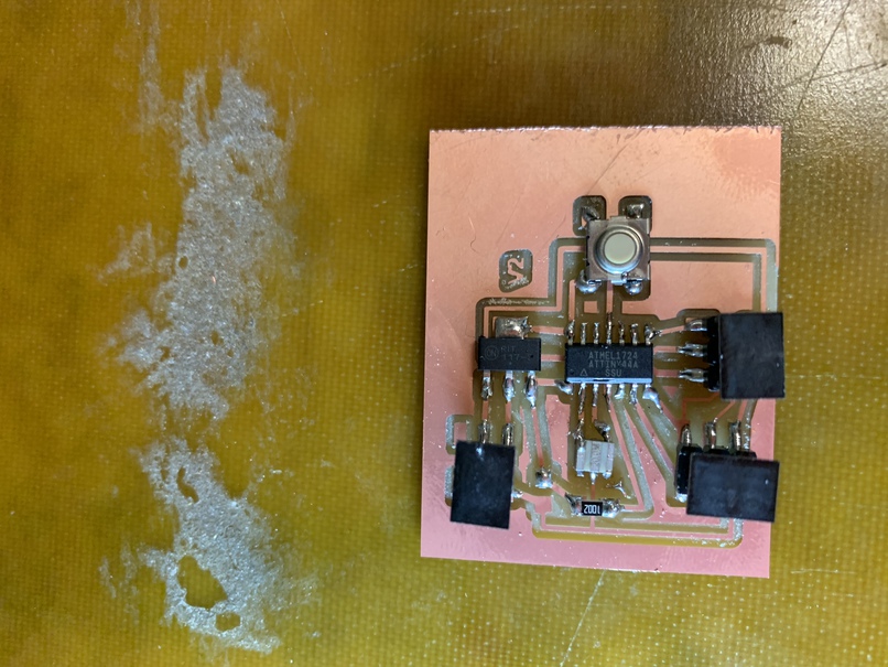
Final debugging
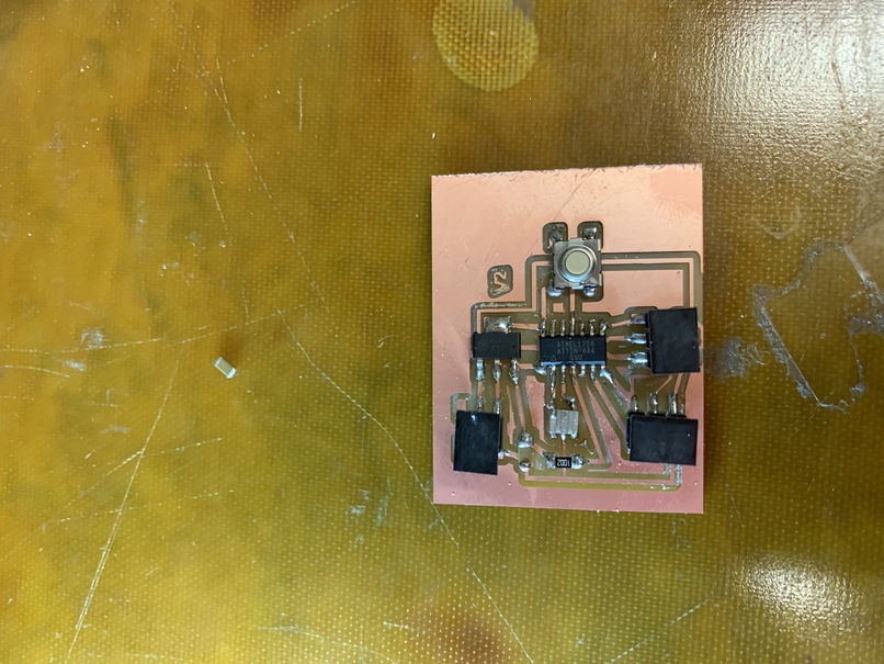
Lol, it works.