Output Devices
"An output device is any piece of computer hardware that converts information/DATA into a human-perceptible form or, historically, into a physical machine-readable form for use with other non-computerized equipment." -Wikipedia
Group Assignment
1. My group measured the power consumption of an output device.
A classmate in the Architecture section, Se Hwan Jeon, was able to acquire a USB power monitor to direclty measure the limits of power available from a computer USB port (Fig. 1A).
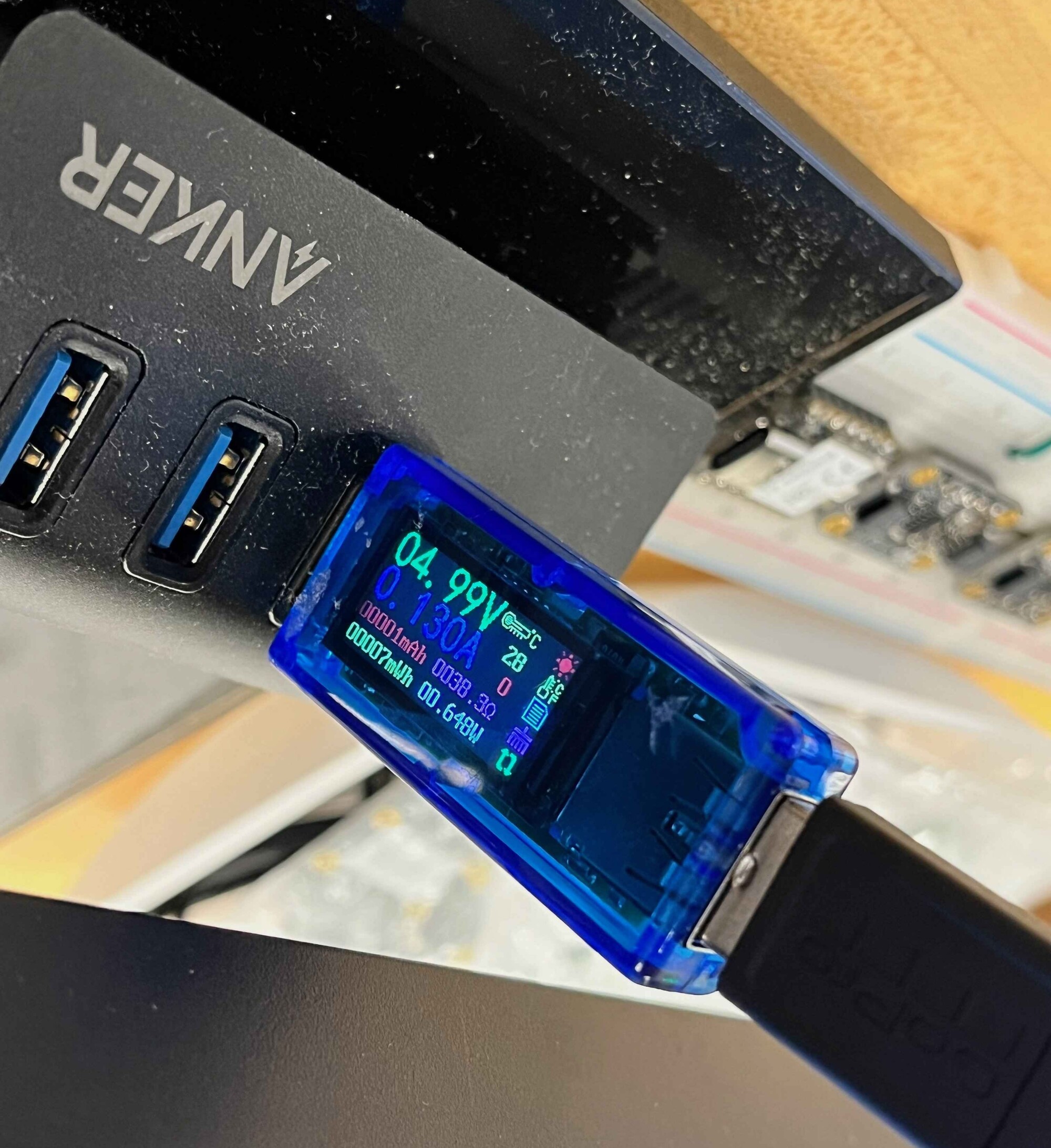
Fig. 1A. Measuring power consumption via USB.
Se Hwan confirmed the measured current draw was similar to that recorded by a multimeter. Furthermore, he measured the power consumption of a servo motor and encoder to be around 0.7 W.
Individual Assignment
2. I added motor pumps to the circuit for my final project and made a PCB to operate them.
In Week 09 I created a circuit for the buttons and OLED display in my Final Project. This week, I incorporated motor pumps and air valves to allow inflation and deflation of blood pressure cuffs that will be used for the contractions of the gut (Fig. 2A). I first acquired some N-MOSFETs, diodes, DC motors, and resistors that I could use to make my initial circuit. To get started with these components, I watched many YouTube tutorials on how to operate a DC motor using an Arduino (Fig. 2A). One video, which demonstrated the building of a circuit to operate a DC motor controlled by a potentiometer, helped me build my circuit (Fig. 2B).
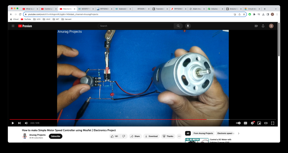
Fig. 2A. YouTube tutorial.
Fig. 2B. Controlling a DC motor with a potentiometer.
As I did not want to include a potentiometer in the circuit, I simplified the design (Fig. 2C). To connect an output device to this circuit, simply connect the two wires of the output device to the two sides of the diode so that the output device and diode are parallel to each other.
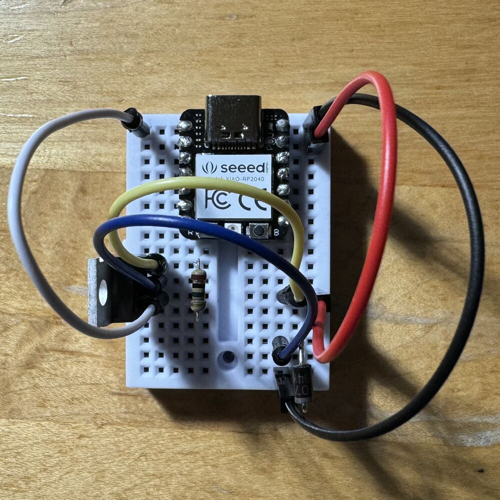
Fig. 2C. Simple MOSFET and diode circuit to control an output device.
I realized I could just make multiple of the simple circuit above to run multiple output devices. I added a second MOSFET and diode unit and connected a DC motor to each unit (Fig. 2D). I then wrote code in Arduino IDE to run both motors in an alternating fashion.
Fig. 2D. Running two DC motors in an alternating fashion.
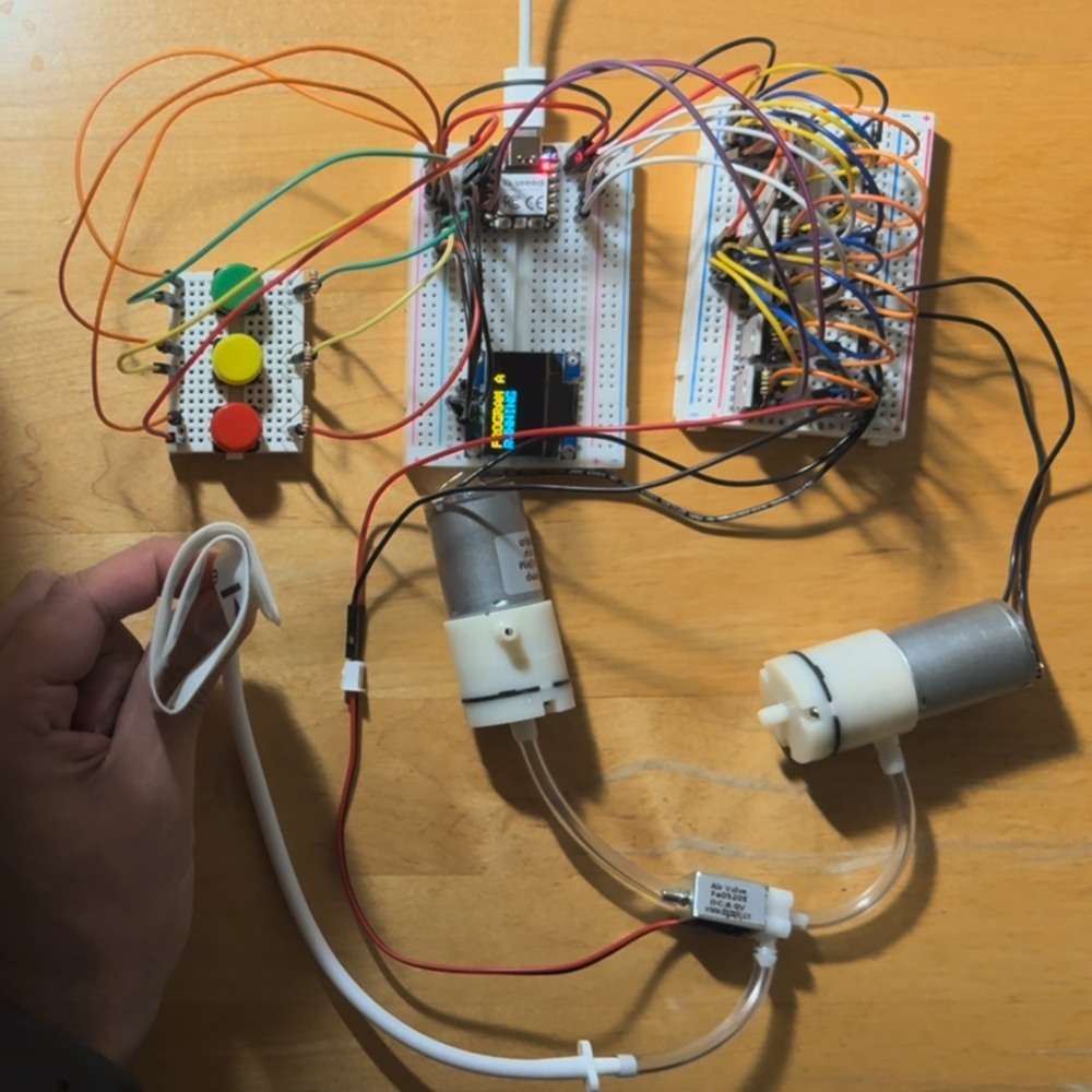
Confident with the setup to run output devices, I added a third MOSFET and diode unit and then added three output devices: two motor pumps and an air valve (Fig. 2E). I connected the motor pumps and air valves to allow for airflow in one and out of the other when the motors are running. I then connected the common tube of the air valve to a neonatal blood pressure cuff, a device I will be using to achieve a radial squeeze.
Fig. 2E. Inflating and deflating a blood pressure cuff.
Ultimately, I will want to have four blood pressure cuffs. These cuffs can be controlled by six output devices: two sets of two motor pumps and an air valve. In the final design, cuffs 1 and 3 will always be contracting and relaxing at the same time, while cuffs 2 and 4 will be doing the same. Therefore, the common tube of an air valve can be split into two to control two cuffs at once. As these modifications will need to be made with the tubing and not the electronics, I just focused on completing the circuit with one pair of motor pumps and an air valve. To do so, I took the button and OLED display circuit from Week 09 and combined it with the circuit I just made (Fig. 2F).
Fig. 2F. Combination circuit of input devices and output devices.
This combination circuit is nearly the final circuit design, and it only missing another 3 MOSFET and diode units to control another set of two motor pumps and an air valve. As making this final circuit would be trivial, I decided to convert the design into a digital version so that I could create a PCB. To start, I found out that I could simulate a circuit on Tinkercad, so I created the simple MOSFET and diode circuit and simulated its operation with a DC motor (Fig. 2G). Making the circuit here also allowed me to generate a circuit diagram, which I used as a guide to make the circuit in Fusion 360 (Fig. 2H).
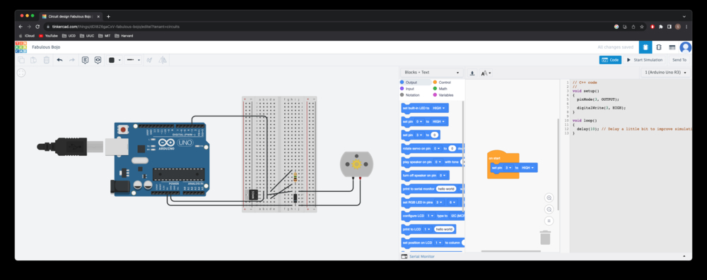
Fig. 2G. Circuit simulation on Tinkercad.
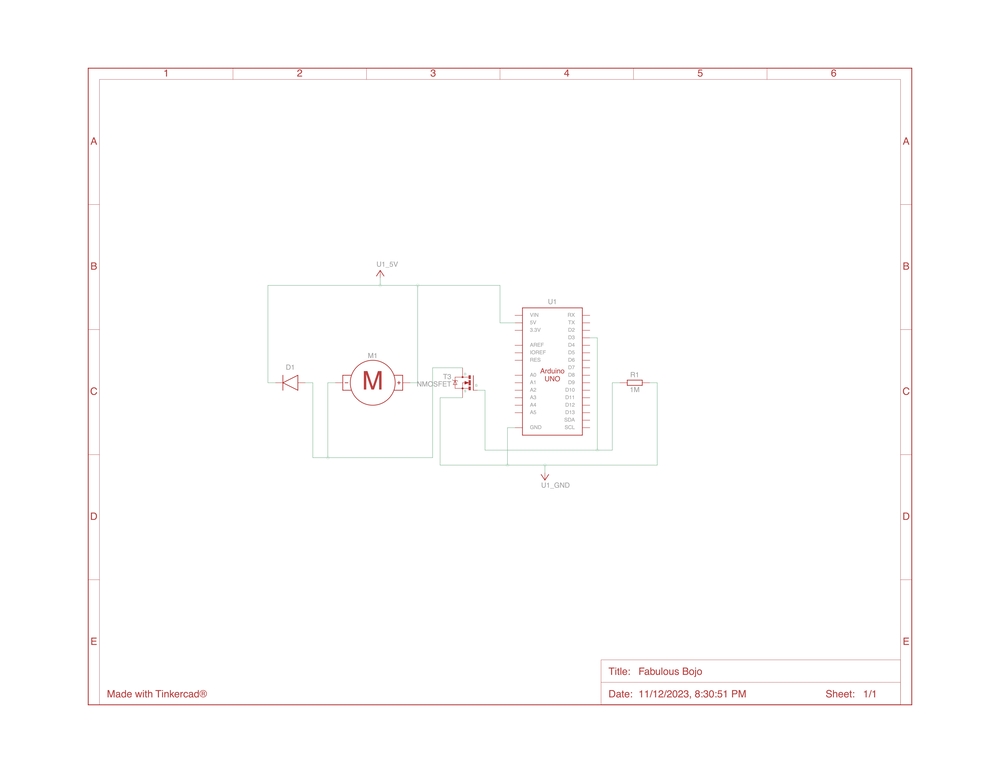
Fig. 2H. Circuit diagram generated from Tinkercad.
I recreated the circuit on Fusion 360, using the skills I learned in Week 05 (Fig. 2I). However, when I went to the Architecture shop to see if we had the components to solder to this board, I realized we did not have the 3-pin connectors I included in the diagram. I therefore had to redesign the circuit with only 2x1 and 2x2 pin headers (Fig. 2J).
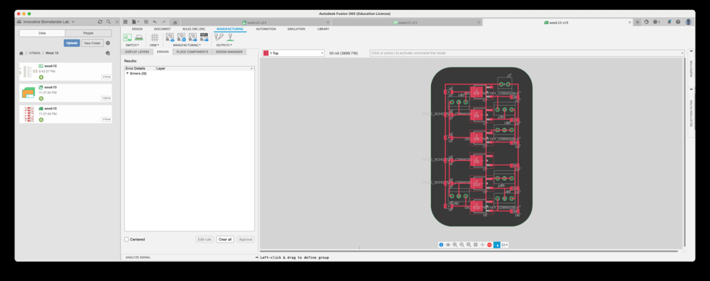
Fig. 2I. Designed circuit in Fusion 360.
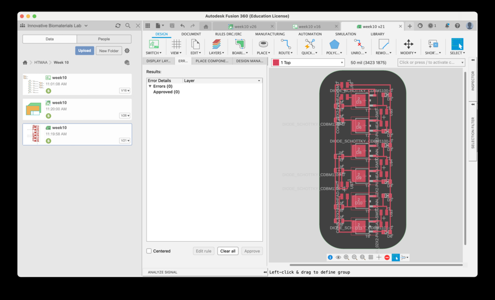
Fig. 2J. Redesigned circuit in Fusion 360.
When I was happy with the design, I set up the Modela SRM-20 PCB mill using the mods program (Fig. 2K). I then started the mill (Fig. 2L).
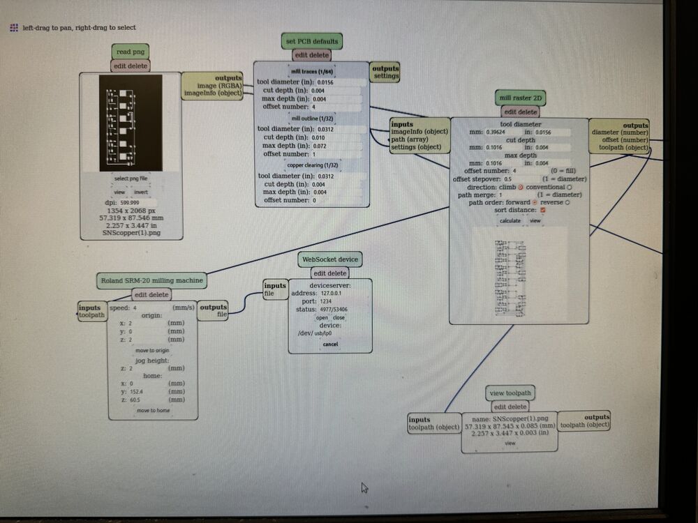
Fig. 2K. Setting up the PCB mill.
Fig. 2L. Running the PCB mill.
The most satisfying part of the milling process is using the vacuum to remove the excess material once the mill is complete (Fig. 2M)!
Fig. 2M. Vacuuming the excess material from the PCB.
After cutting the outline of the PCB, removing the finished board, and washing it with abrasive soap, I secured it to a piece of cardboard along with my components and began soldering (Fig. 2N). The soldering process took three hours (Fig. 2O). When it was finished I could not wait to connect it to my circuit and test it out.
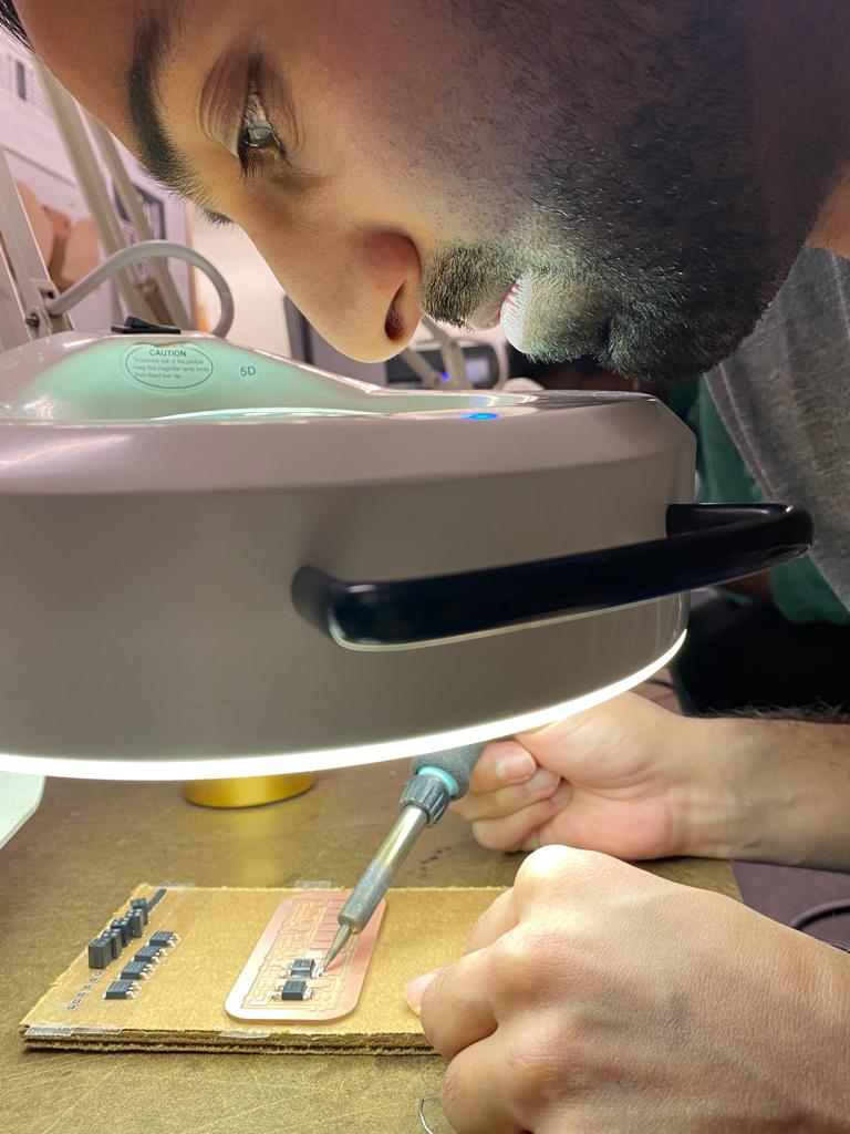
Fig. 2N. Soldering components to the PCB.
Fig. 2O. Soldering process.
After replacing the breadboard with my MOSFET and diode units with the PCB, I tried running the program, but unfortunately the motor pumps did not run (Fig. 2P). This was very frustrating after spending an entire day designing and making the PCB. Troubleshooting why it failed, I actually found several problems with the circuit diagram I drew in Fusion 360. First, I connected all of the 2x2 connectors to the motor and GND, when instead they should have been connected to the motor and 5V. Second, I connected the terminals of the MOSFET to the other components incorrectly. Looking back, I should have more closely followed the circuit diagram I generated from Tinkercad when drawing it in Fusion 360.
Fig. 2P. Attempting to run the PCB.
Now that I realized the mistake, I can fix the PCB design easily for the final project. In the meantime, I made the final circuit on a breadboard, which has the same functionality as what the PCB should have had (Fig. 2Q).
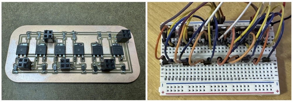
Fig. 2Q. Equivalent PCB and circuit.
Testing the final circuit, it works (Fig. 2R)! The .ino Arduino code for this circuit can be downloaded here. While I only connected one set of pumps and air valve here, the circuit has the additional MOSFET and diode units to control the other output devices. With this final circuit design, I will work over the next few weeks to convert it to a PCB.
Fig. 2R. Running the final circuit.
Overall, I am making good progress toward my final project, how nearly completing the electronics!