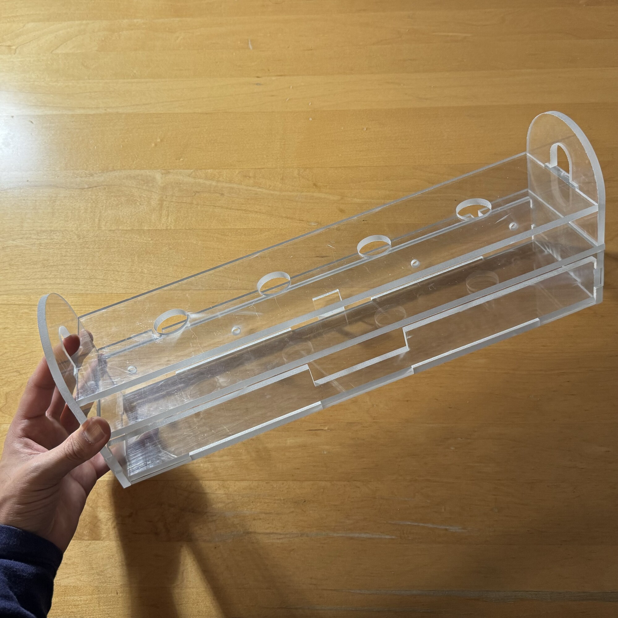
Water Jet Cutting
"A water jet cutter, also known as a water jet or waterjet, is an industrial tool capable of cutting a wide variety of materials using an extremely high-pressure jet of water, or a mixture of water and an abrasive substance." -Wikipedia
Individual Assignment
1. I water jet cut a frame for my final project.
This week was "Wildcard Week" meaning we could pick any skill not covered in the previous weeks to learn and use to make something. I selected water jet cutting, as I assessed it to be very useful for making progress toward my Final Project. The water jet cutter works in a similar fashion to the laser cutter, used in Week 02. This week, I made a sketch of the frame for the gut machine, complete with dimensions, and then created a CAD version that I could use to physically make the frame water jet cut pieces of polycarbonate (Fig. 1A).
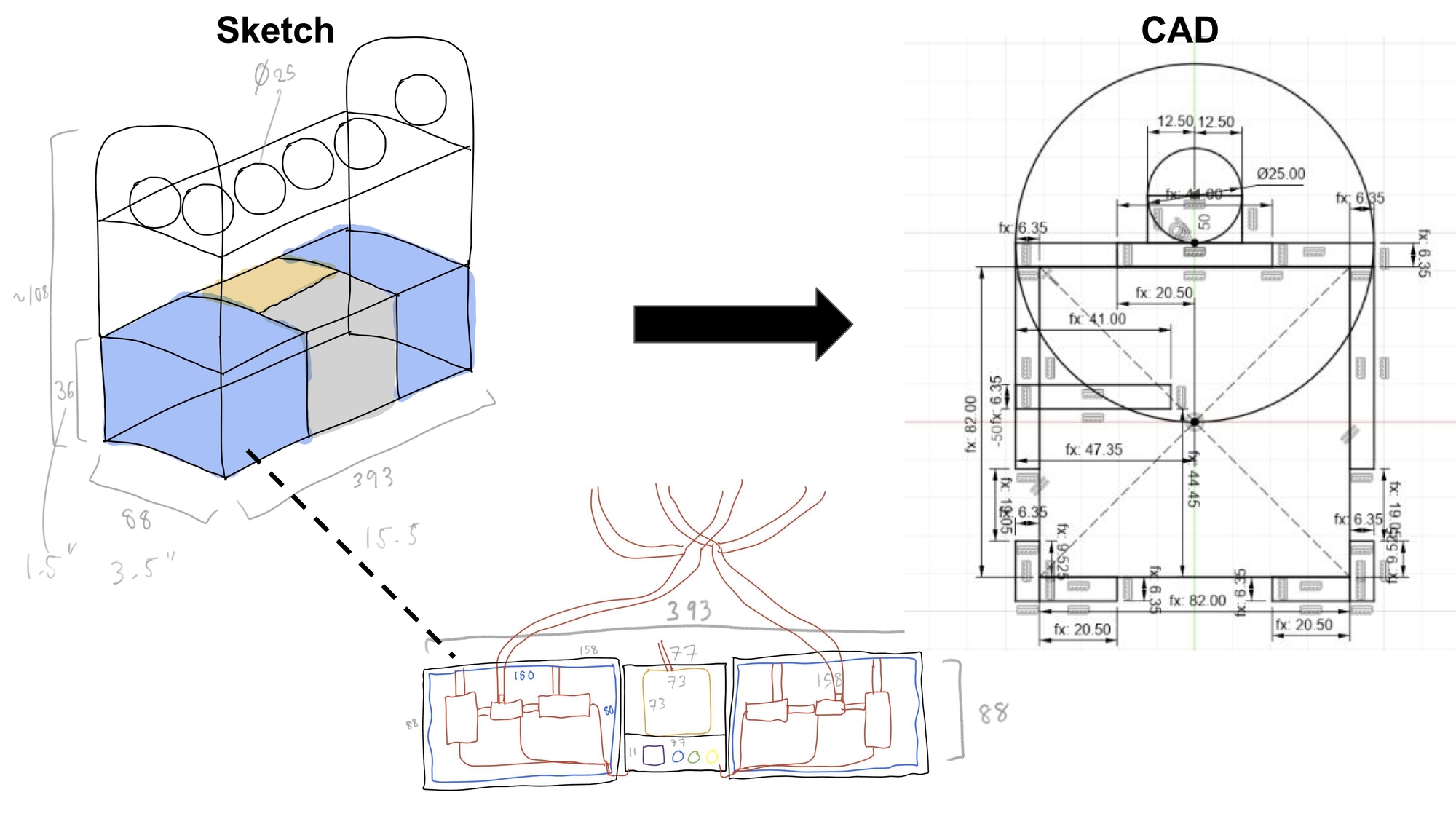
Fig. 1A. Converting my sketch to CAD.
Using Fusion 360, I created each part for the frame, then assembled them to ensure each part would fit together (Fig. 1B). This was an iterative process, having to make modifications to a part and checking to see if it still fit with the others each time a modification was made.
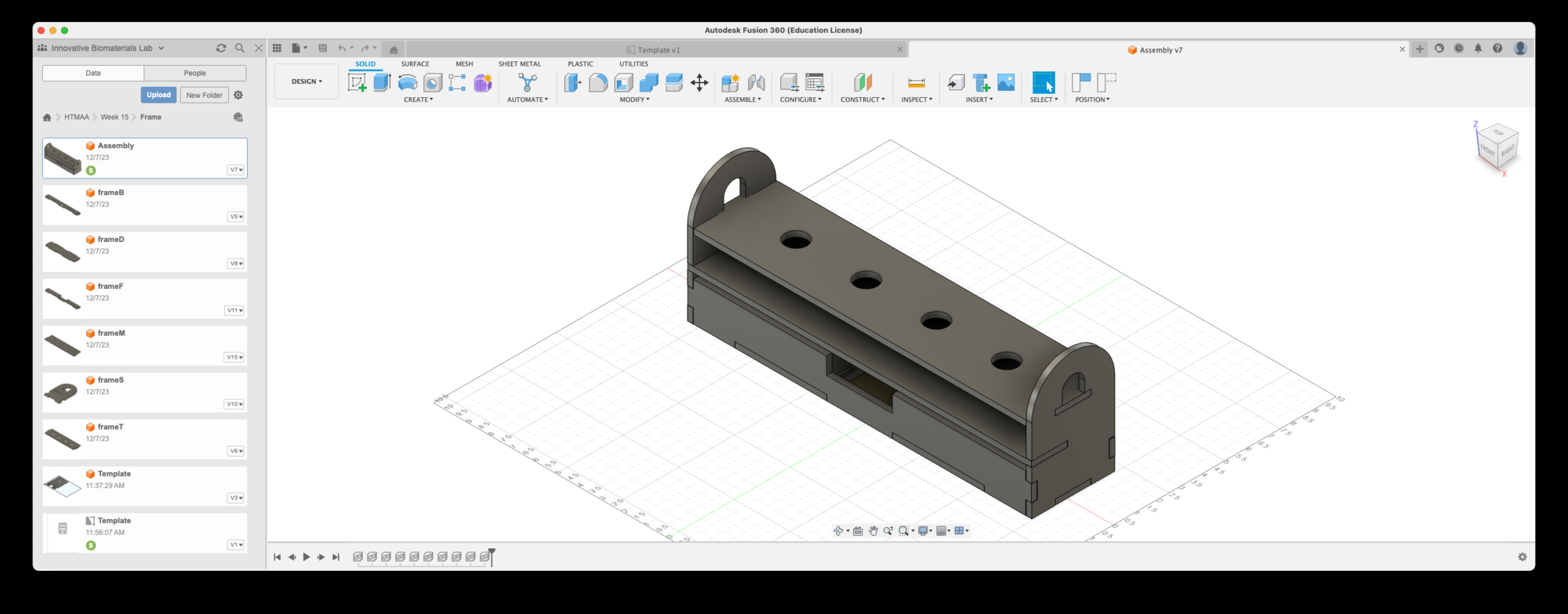
Fig. 1B. CAD assembly of the frame.
When I was happy with the design, I generated a 2D view of the parts and saved it as a .dxf file that was compatible with the OMAX water jet cutter in the Architecture Shop (Fig. 1C). The .dxf file can be downloaded here.
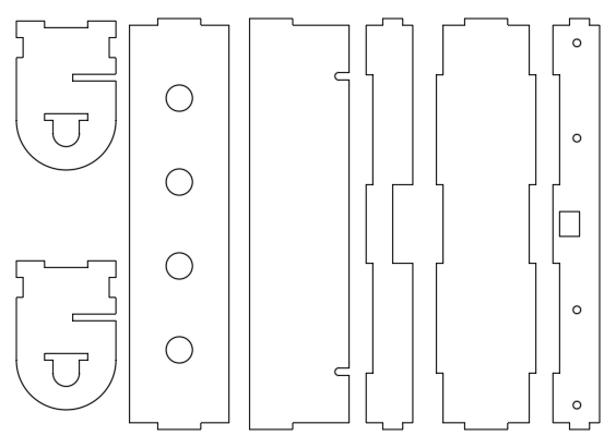
Fig. 1C. Template of frame parts.
The MIT Architecture Woodshop at N51 had some spare sheets of clear polycarbonate. I worked with Chris Dewart who I met during Week 08 who helped me use the table saw to cut a massive sheet (around 4' x 10') of polycarbonate into smaller pieces (Fig. 1D). I brought back two pieces (each around 2' x 3') to the Architecture Shop. It was a workout as these pieces were heavy!
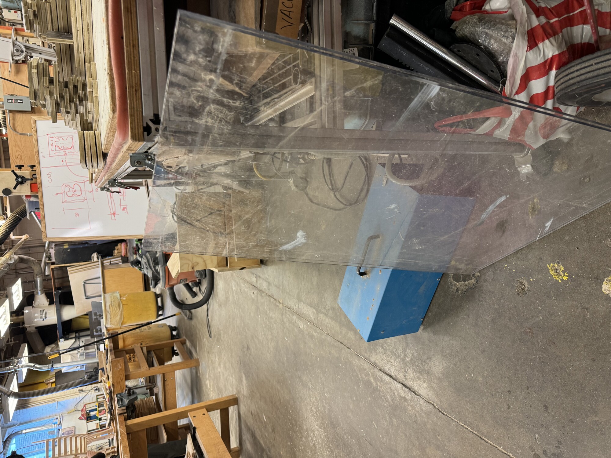
Fig. 1D. Picking up polycarbonate sheets.
Back at the Architecture Shop, Project Technician (and "all-around nice guy") Shah Paul helped set up the water jet cutter. We had to scale up the drawing in the .dxf file as my template was at 1:8 scale, and after doing that it was ready to upload to the machine. He showed me the steps of placing the material in the water jet cutting bed, placing weights on top of the material so it would not move, and calibrating and starting the machine. The entire job lasted around 8 minutes, but after each piece was cut we paused the job to remove the piece to ensure it would not float around in the bed (Fig. 1E).
Fig. 1E. Operating the water jet cutter.
I was very happy with the way the pieces turned out (Fig. 1F)! The tolerances of 0.013" were perfect to allow for the pieces to press-fit together.
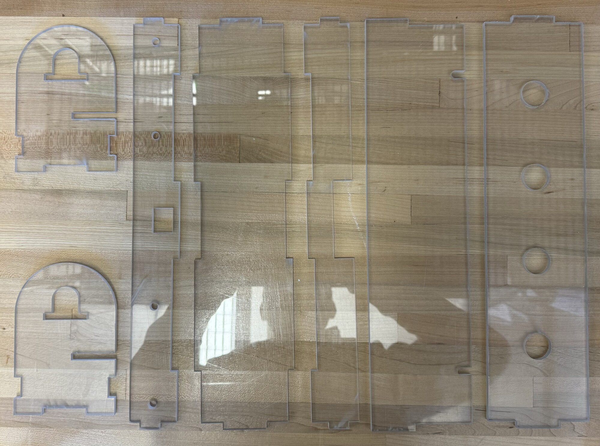
Fig. 1F. Cut pieces of polycarbonate.
I added the functionality of a removable middle layer, uncovering a container at the bottom, which I have planned to house all of electronics of the gut machine in (Fig. 1G).
Fig. 1G. Sliding out the removable layer.
I placed some of the electronic components in the frame to test if the design worked as intended, and was happy to find that turned out perfectly (Fig. 1H)!
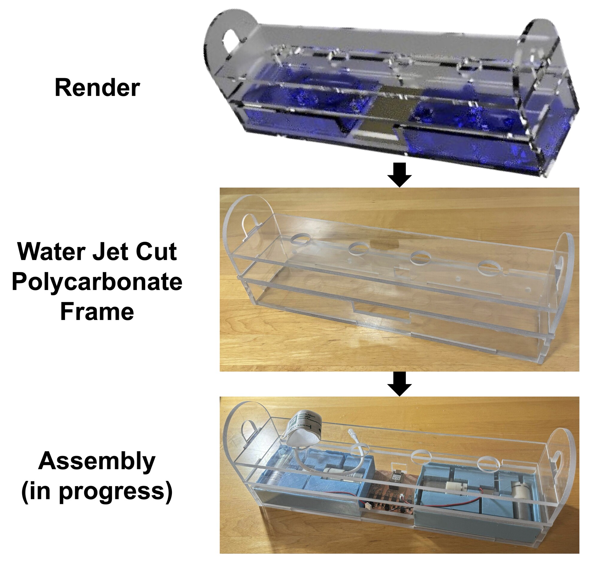
Fig. 1H. The process leading to assembly.
This week was a nice refresher of some old skills and a great opportunity for learning some new ones, and overall I am pleased to have made solid progress toward my final project!