Week 5- Electronic Production
Or how to remake almost everything


This week we went over producing PCBs. In the group assignment, we tested the Carvera. We also talked about using JLCPCB for fabrication.
With this experience under the belt, I went off to make my PCB designed last week. This PCB has some LEDs, buttons, a switch, and two H bridge to control a couple of DC motors.
My board looks like this, after going through the gerber2png tool.
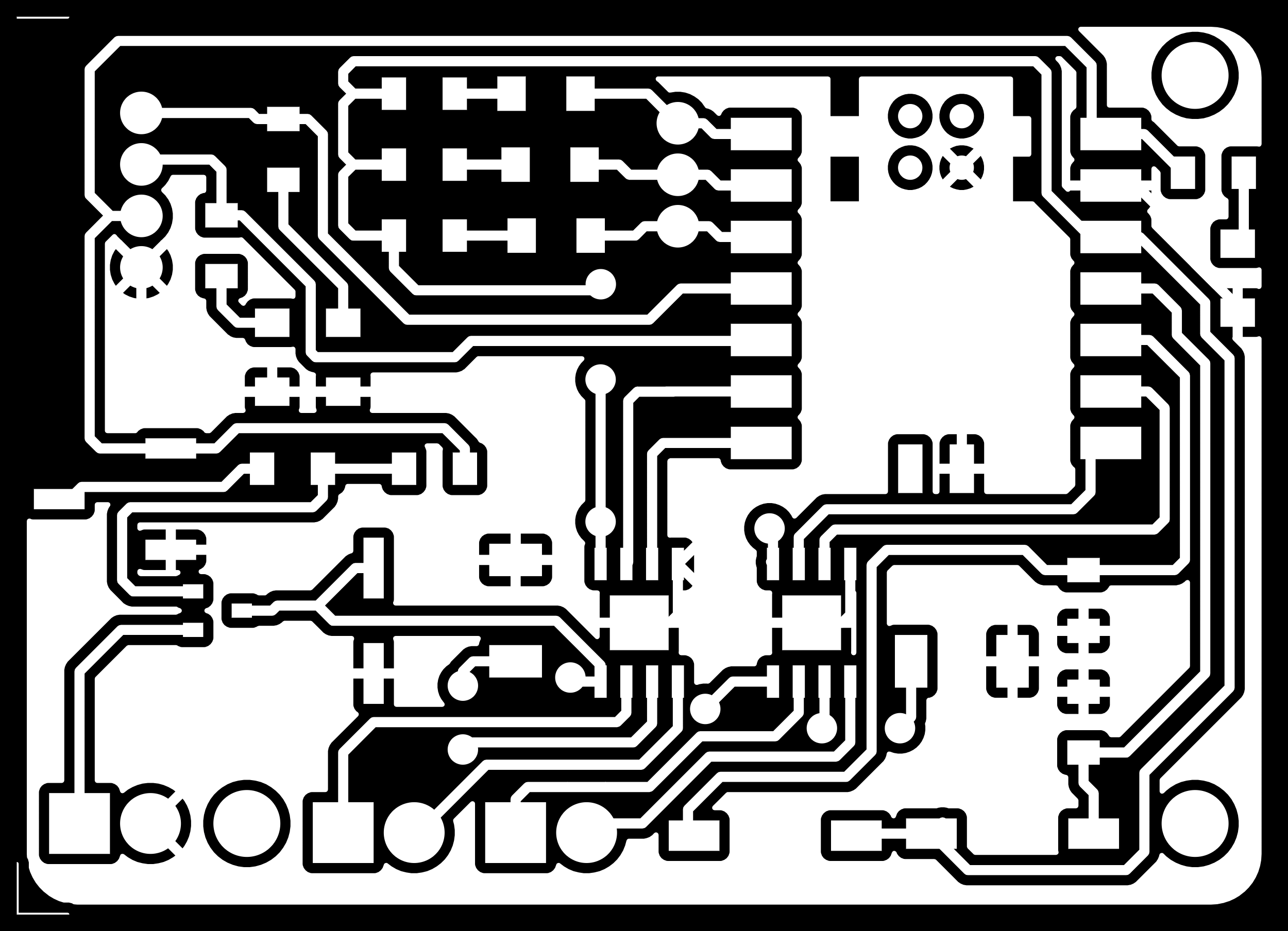
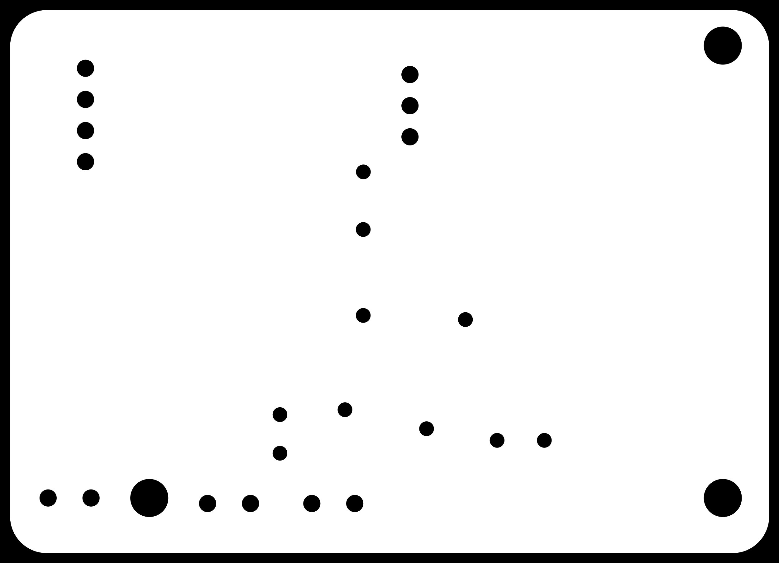
These images get uploaded to the mods tool and the outputing job is saved.
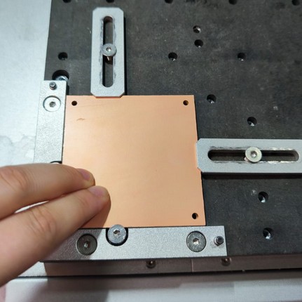
I started with the Canvera machine. First I measured the stock to make sure it would fit my board.

Then set up the machine with the stock, measuring the origin.

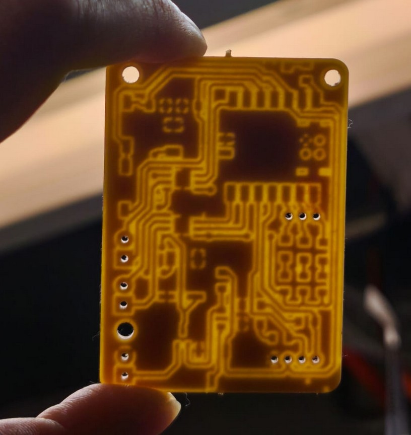
I configured the machine properly, using Quentin's very helpful tutorial as a guide. Then I stared at it without even blinking to make sure it was all good as it probed and switched tools and machined.


It worked. Now it was check and clean. I sanded and user a box cutter to clean some traces that were touching.

I've soldered before, but I really need the mask to make clean soldering joints. I keep making everything turn into cute shiny silver tin. I don't like to have all the copper exposed, it's not good for my eye-hand cordination but it is what it is.
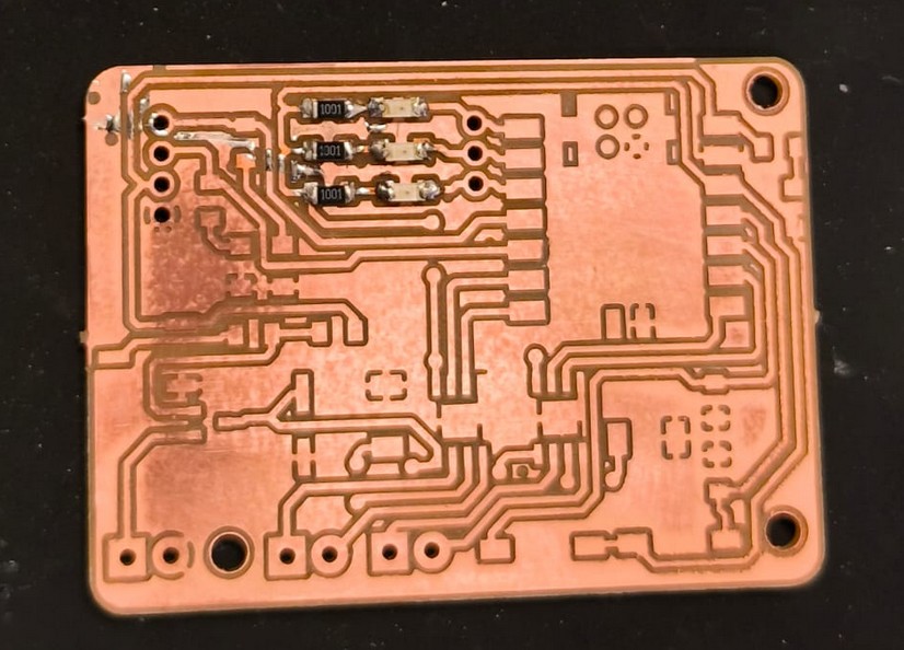
The real challenge, however, was the vias. Originally I designed it as a 2 layer board, but with only 5 traces in the bottom layer, I figured it was not needed. I noticed the via diameter was too small for the machine to drill, but did not think to change the diameter. I knew I would have a pad to solder a wire, and I could just make the connections above over the board. At first, I used a cable with braided wire, which sucked. I spend 3 or 4 hours solderng these tiny cables, maganing only the two biggest ones.
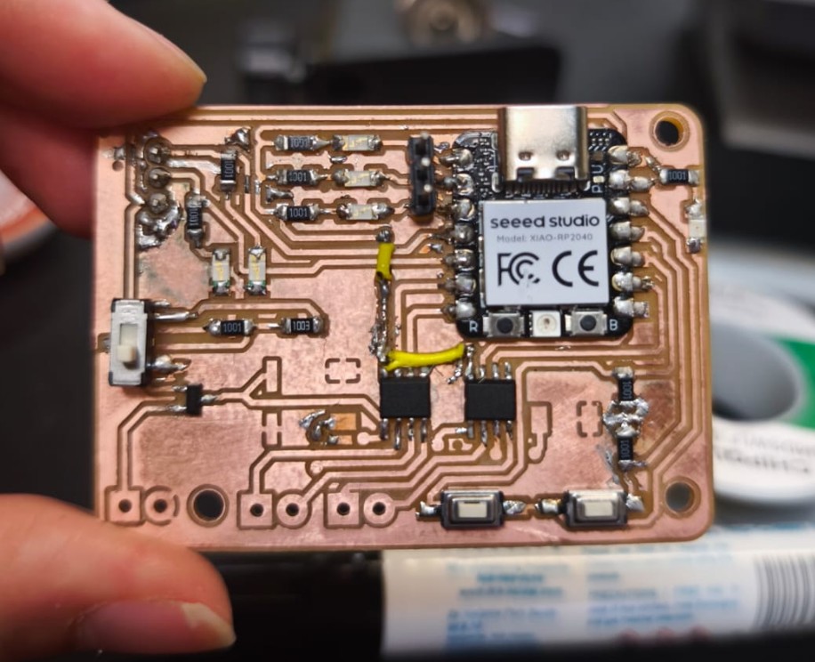
Kristof walked past being very nice and friendly and noticed I had been there for a while. He took pity on me, and found me a single strand wire to end my misery. Thank you Kristof.
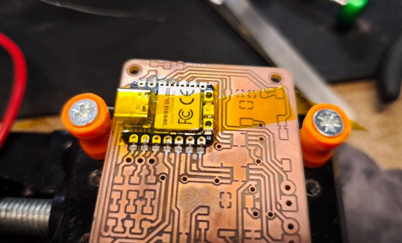
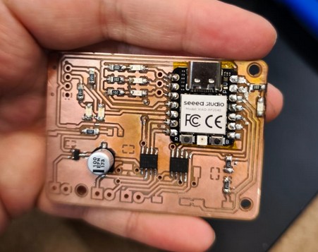
After three days, I finally had my soldered board ready. I was ready to test. I did the most important check first- continuity between voltage and ground.
It beeped.
This was not the short I wanted or needed in my life.
So I went full into debugging mode. I checked all the traces. I checked all the soldering joints. I remove components and the short was still there.
The only component I had not desoldered to check was the MCU. Was it the Xiao all along?
I stared at it more closely and noticed my janky soldering actually had it up in the air, slightly, and there was some solder under it. Was it enough to cause a short? Was the pads under (which includes a Vin) in contact with the ground plane?
So I had to desolder it. Gotta bring the big (heat) guns.
Did anyone order crispy PCB? I might've burnt a lil bit of it.
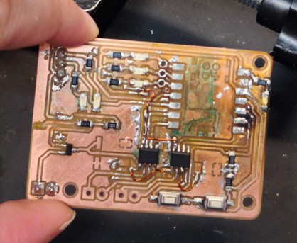
With the microcontroller out of the way, I checked the pads both on the board and on the XIAO. I found they did not short at all. This confirmed it was my soldering that was shorting the boards. So I soldered again super carefully. And it shorted again. So I desoldered it again. And this time it looked very burnt, so i thought it would be best to remill it. Since I was remilling it, I should fix the vias and make it easier to solder the next time around.

I checked the vias will be drilled- success.
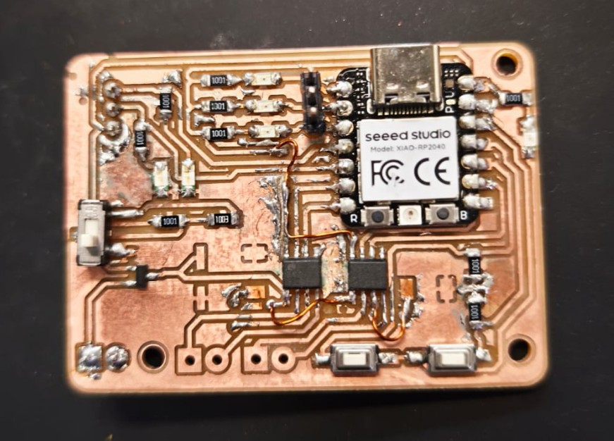
I had a brand new, non-crispy, extra special board.

I started with the MCU this time, and I checked the pins as I was soldering one by one to check there was no short. I held it down with tape to make sure it wasn't floating. I put tape on the bottom to make sure the pads werent touching anything. And I was ready.
It shorted.
Again.
Even the pins I had checked before now everything is connected. What is even happening?
Desoldered, again.
Probed all of it. Nothing was shorted in the XIAO. Nothing was shorted in the board.
I spoke very sternly to it. In Spanish. To intimidate it.

I also found the tiniest of shorts in one of the traces close to a pad so I fixed that.
One or both of those two fixed it. I soldered the rest.
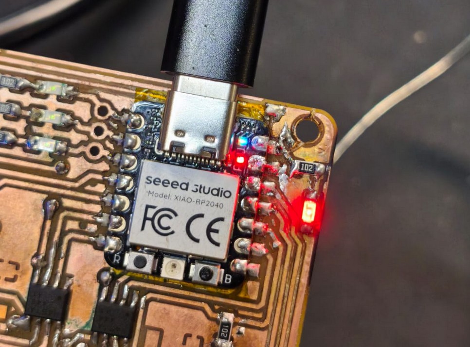
Beautiful, great, functional- or so I thought.
I probed again, found some mistakes from soldering and other traces touching. I was finally confident enough to plug it into the computer and test the code.
Some worked, a lot of it didnt. So i started debugging piece by piece. I couldn't test the H bridges yet because it requried a 0.25 ohm resistor as reference, and that is not in stock (yet). But I could test the signal, I used an oscilloscope and that showed it was working.

I could test the buttons and the LEDs and the display, as well as the PWM signal going into the H bridges. I used a code generated by ChatGPT for this. The code controls the motors, reads the buttons, and in the display you can change modes to change the speed of one of the motor, the other, or both as well as an E-STOP depending on the combination of presses of the two buttons. Because we only had two buttons, it was necesary to get creative.
make a code for the seeed xiao rp2040 using the arduino ide. it has three debug LEDS in D1, D2 and D3 in low side logic. I has a oled pixel display 128x32 that uses Adafruit GFX + Adafruit SSD1306 library. It also has two dc motors controlled through drivers that have two inputs (TB67H451FNG,EL). The idea would be that there are three modes of control. The display will show which mode it is, and you can select the modes with the buttons. on the first mode, one button controls one motor at a set speed. In the other two modes, you select which of the two motors you want to control, and you can lower the speed or make it faster. If you press both buttons it switches direction. If you press for long enough both buttons it goes back to mode selection, where you can cycle through using one button and use the other to select as mode. |the display has the menu and also instructions to use the buttons correctly
However, it needed some back and forth to get it working properly. I had to add some debouncing, as well as fixing some logic errors. But after some time, it worked!
TODO: resistors are here two weeks after, I should come back and test
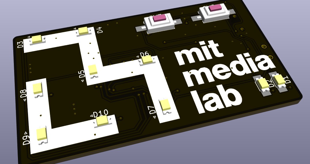
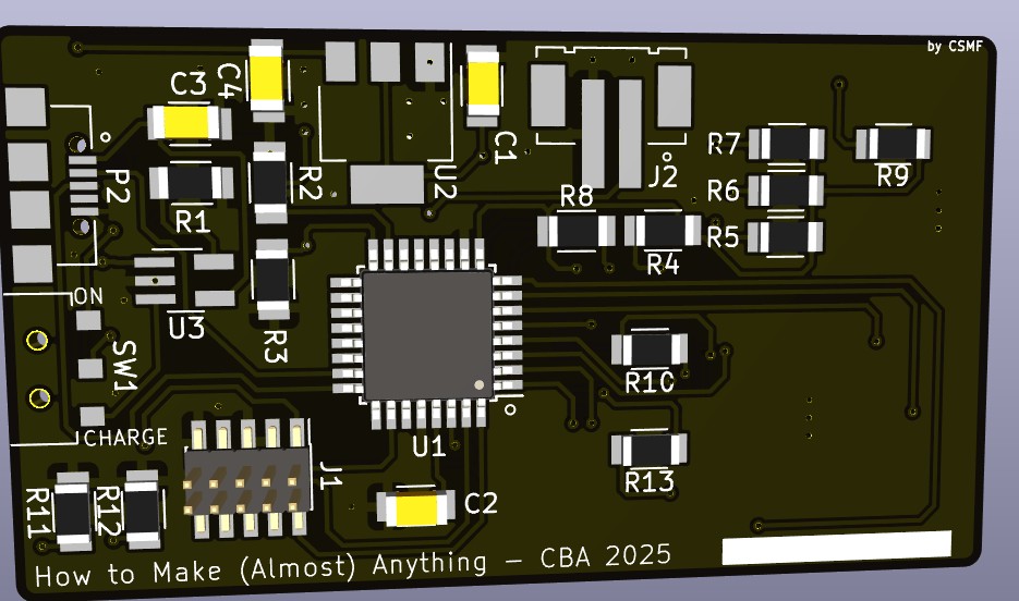
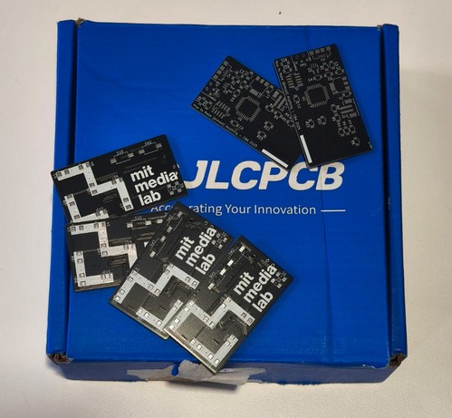
In addition to this board, I designed a board to send to a manufacturing house. Since a lot of us in the CBA section are affiliated with the Media Lab, and the class is within the Media Lab building, we figured we could order a board together with somehting about the Media Lab. So I designed a board with the Media Lab logo and some LEDs that would light up according to how they were programmed using a SAMD21 microcontroller. We ordered it through JLCPCB, which was super easy to use and had great prices, coming up to about $31 for 30 boards, and it arrived in exactly 1 week.
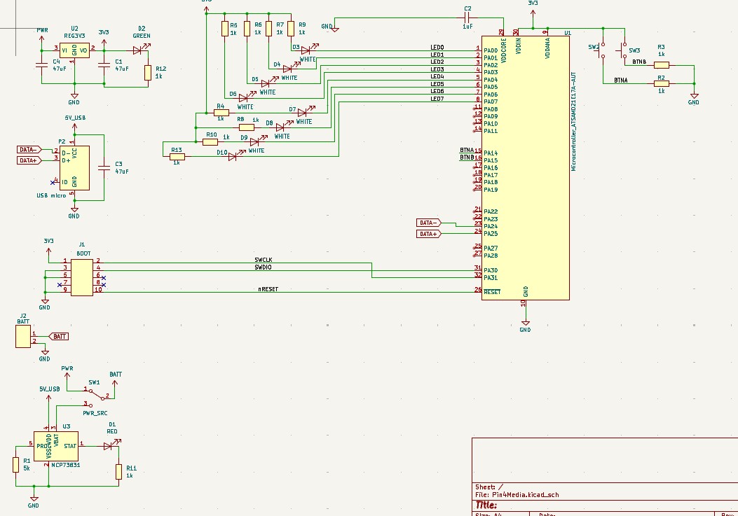
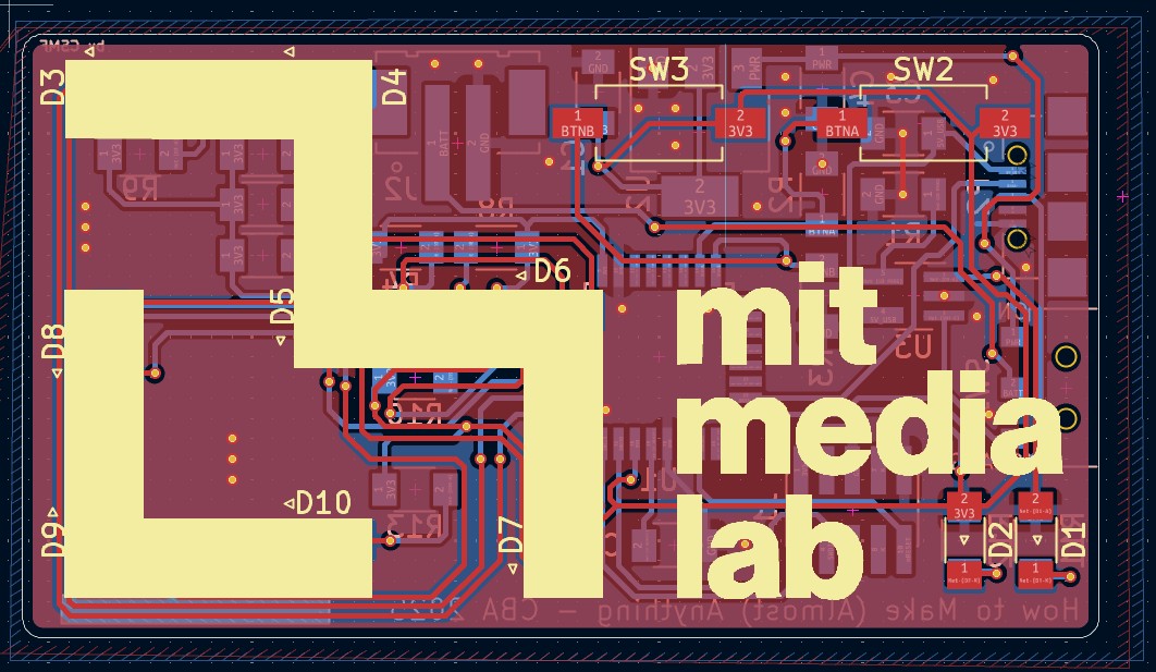
You can find the files for this PCB here: schematic and PCB.