Week 7- Inputs
Is it hot in here or is it just me?

Input week is upon us, and I decided to use the one input device that will be important for my final project: temperature sensors.
In the past, my lab changed from using a thermistor to using RTDs (resistance temperature detectors). I wanted to compare both types of sensors,
so I used a MAX31856 (thermocouple amplifier from Adafruit breakoutboard) and a MAX31865 (RTD amplifier from Adafruit breakoutboard) to read both types of sensors.
Additionally I wanted to make a Wheatstone bridge circuit to read the RTD directly. This bridge consists of 4 resistors, one of which is the RTD, and the output voltage is proportional to the resistance change of the RTD as temperature changes.
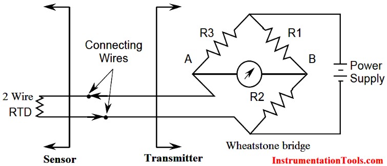
The wheatsone works by comparing the difference, so often we can use a differential amplifier to read the output voltage. I wanted to use an AD8606 rail-to-rail op-amp to make a differential amplifier circuit. However, as I didn't have a negative voltage source, I left it just as a breakout board to read the Wheatstone bridge output directly with the microcontroller ADC and then if I had time I would experiment with a single rail OpAmp.
I also used an RTD in a straight voltage divider. With these four - MAX31856, MAX31865, RTD (wheatstone) and RTD(voltage divider) I can do a fun comparisson of four types of temperature reading.
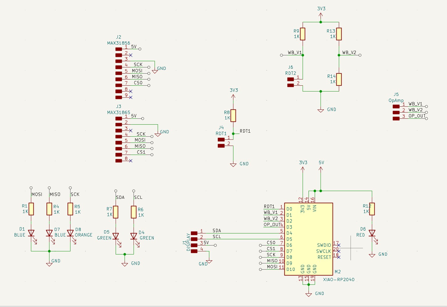
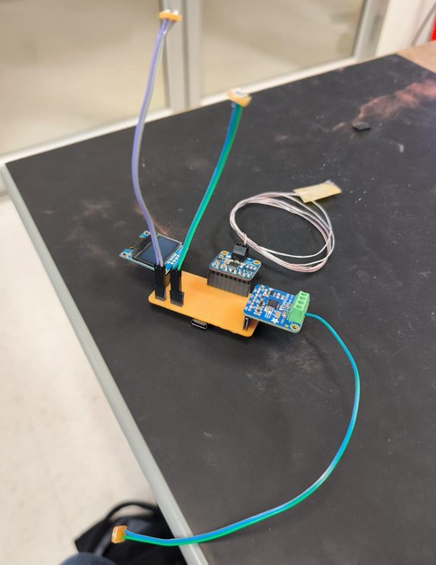
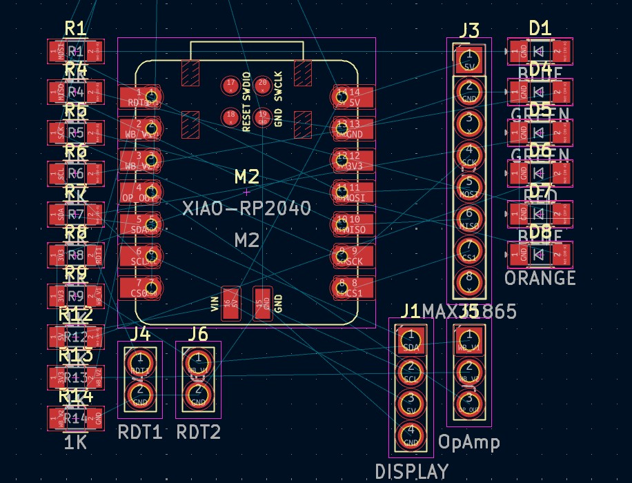
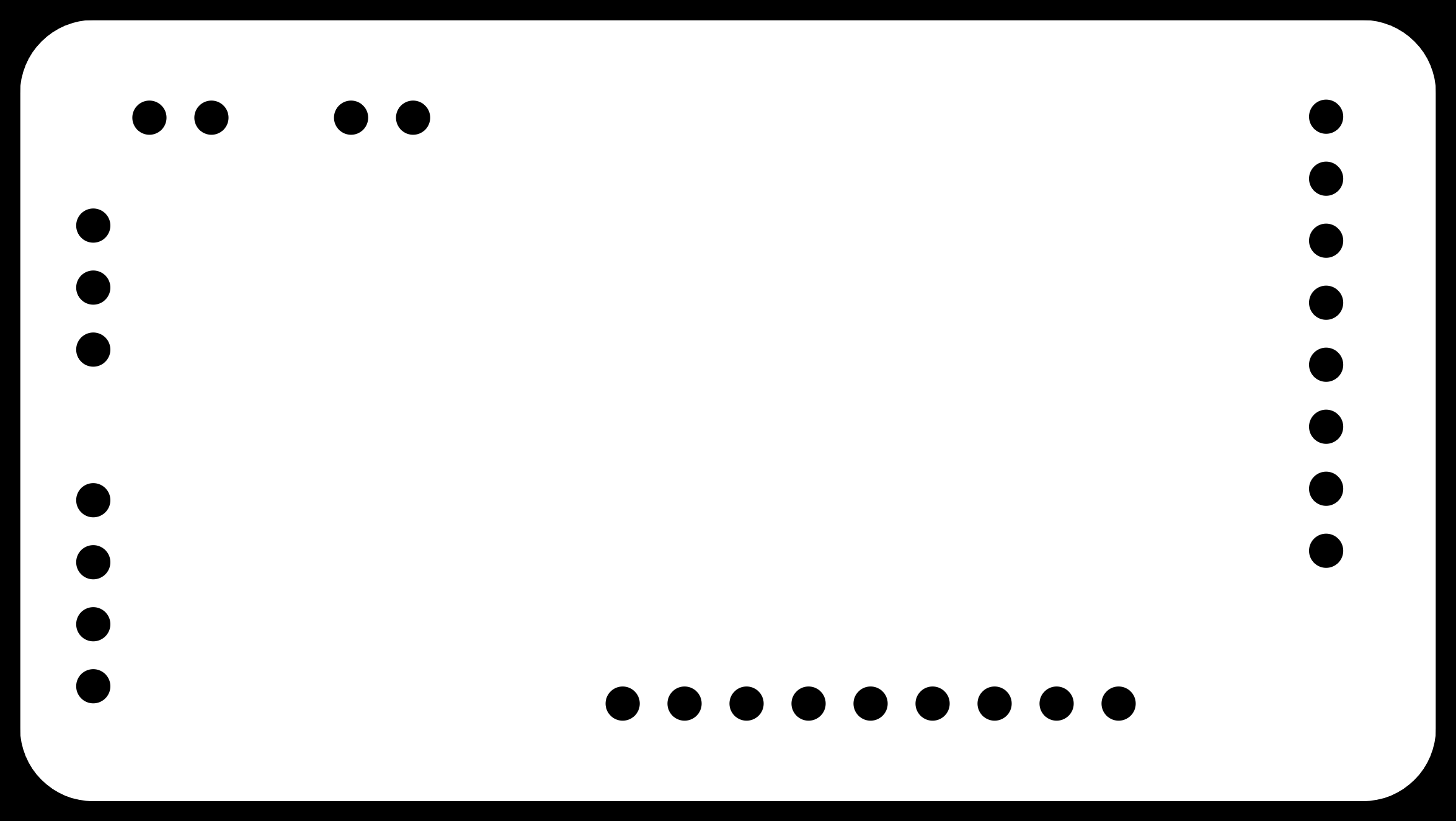
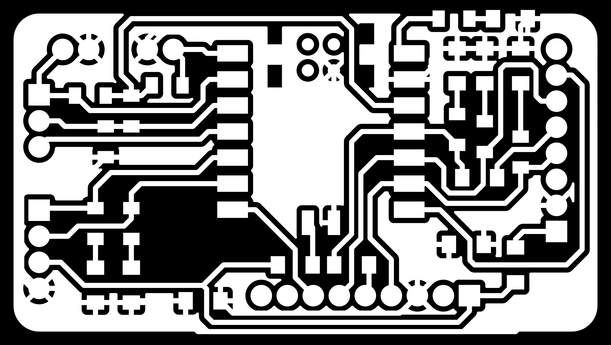
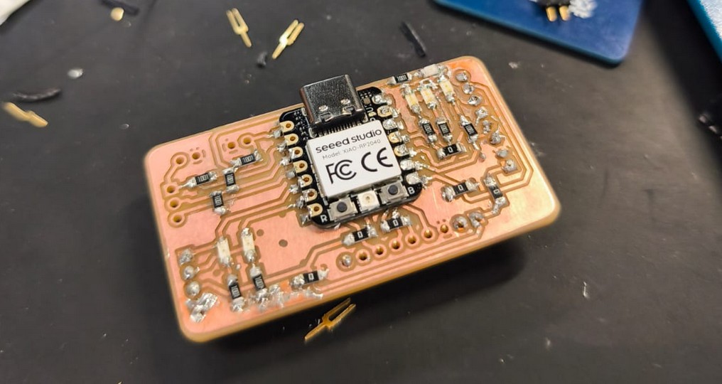
For the fabrication, I designed a small PCB to hold all the components and make the connections easier. The RP2040 would have SPI communication with the breakout boards, and analog readers for the wheatstone and voltage divider. I used KiCAD to design the schematic and PCB layout, and then exported the Gerber files to be milled in the CNC machine using mods.
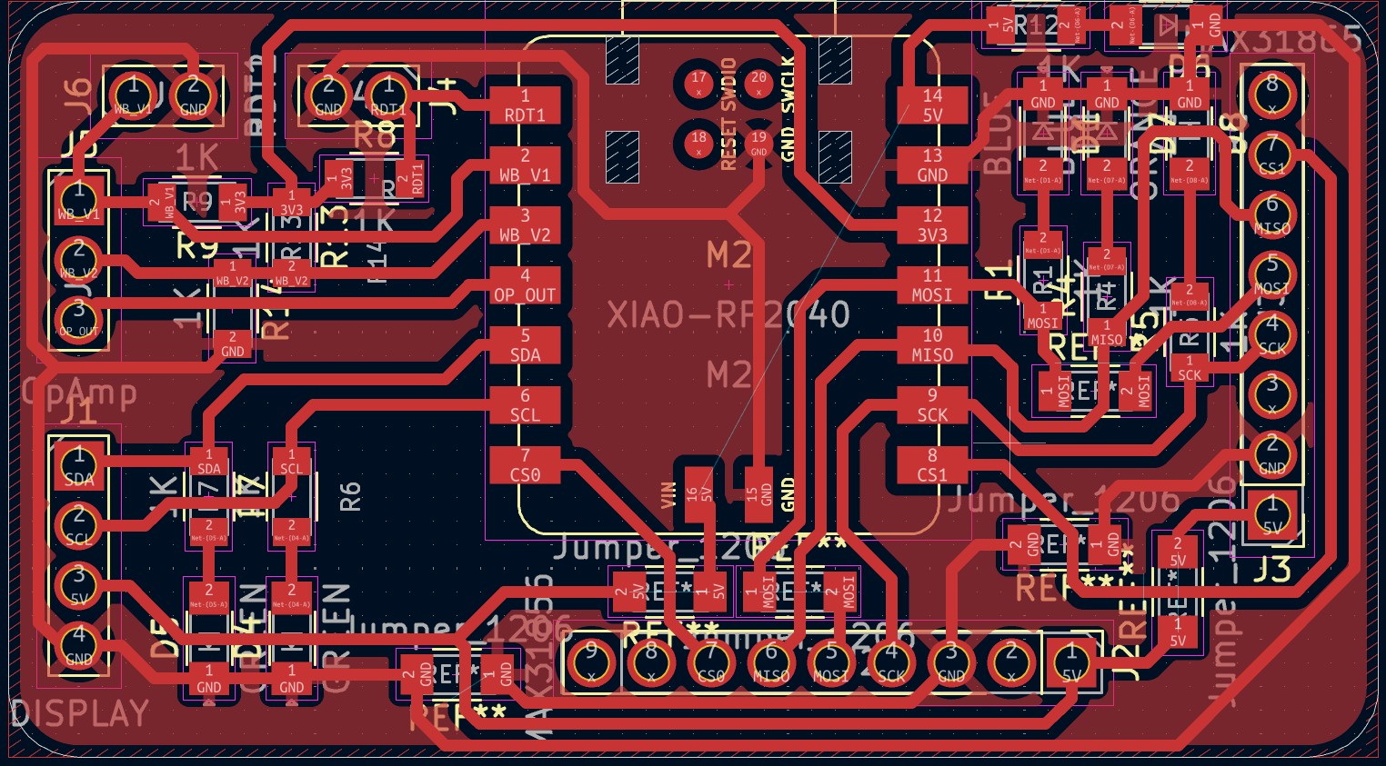
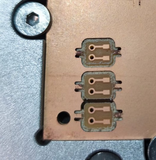
As usual, the Carvera milled the board perfectly, and I soldered all the components carefully.
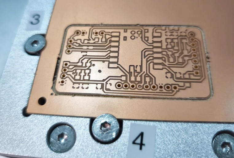
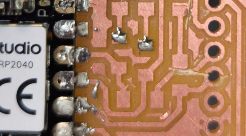
Well, almost. I had some traces that weren't separated enough so the milling machine didn't cut them properly. I had to use a knife to separate them and fix the mistakes. However, I accidentally cut other traces in the process.
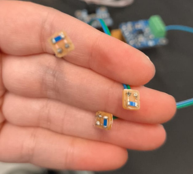
I managed to solder everything and fix the issues that I could see with the board. The connection seemed all good, but I was missing something important. You might have noticed in the schematic that the RDTs were headers and not the resistor symbol. This is because I did not want the RTDs to be connected to the board, but to be able to function as a probe and read temperatures away from the board. However, the RTDs do have an SMD 1206 package. This is why I needed to do a new tiny board to create the connections with the RTD. This board has the RTD and two holes to solder wire to.
You would've thought this was the easiest board ever, and it was so easy to design but the manufacturing had some issues.

These beautiful files broke mods.
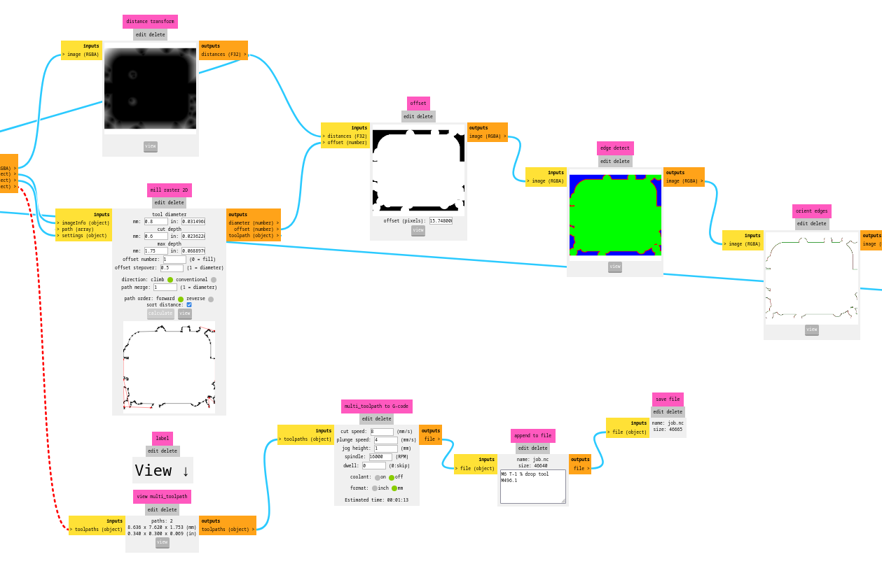
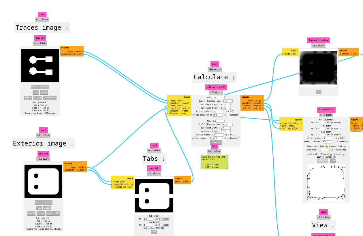

For some reason, they said absolutely not. Others in the slack channel tried my files and had some issues but not this bad. Matti did discover when using GIMP you could move the curves enough to find noise in other colors in the places where the error was happening.

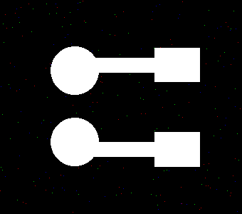
The color noise does correspond to the errors in mods. However, Neil and others could not replicate my issue. In the end, Matti sent me the files he generated and I was able to mill the tiny board.
This allowed me to hook up the whole thing.
One thing I noticed too late was that I forgot the pull up resistors for the I2C bus. This meant that the display would not work, so I could only test with the serial monitor.
I tested it with code generated with ChatGPT.
My prompt went like this: code for a rp2040 xiao that has analog read on pin d0 for a potenciometer (call it voltage divider rtd), d1 and d2 are also analog read and substract them, the difference call it wheatstone bridge rtd. Using SPI, it is communicating with a max31865 and reading a temperature (call it max rtd). The cs is connected to pin d7. Also in SPI, its communicating with a max31856 and reading a temperature (call it thermocouple) and using the cs in pin d6. It has a 128 x 32 oled display using i2c, please print on this display the four temperatures (voltage divider rtd, wheatstone bridge rtd, max rtd and thermocouple) and update the readings every second. Have an icon on the corner to show when a new reading has been done.
There was a lot of trying to debug the display before I realized my mistake. The serial monitor however showed all four readings perfectly.
Final project uses the MAX31856 thermocouple amplifier, please check there for more details.