Week 8- Output
Motors should go brrrrmmmm

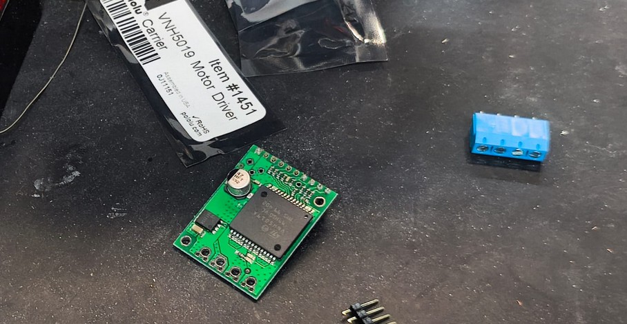
This week was all about outputs. I decided to continue advancing with my final project, so I used the DC motors and drivers I need for it. This are VNH5019 Pololu drivers connected to Pololu DC motors.
As a reminder, my final project is to make a benchtop version of centrifugal casting of wax. This means I need to make it spin spin. And there is a lot of old motors in my lab from past versions of the experiment, which is why I chose this specific Pololu versions.
I am using KiCAD 9.0 for all my electronics design.
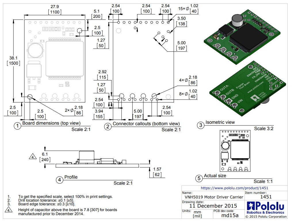
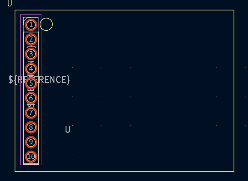
I decided to make a schematic symbol and footprint for the Pololu driver, mostly so my board didnt have the driver hanging off in the air. If I get time, I would love to design a case for this one, so I want it all to be neat. So for starters, I needed the info on the driver, which Pololu kindly provides.
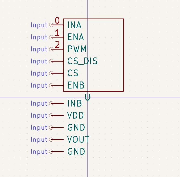
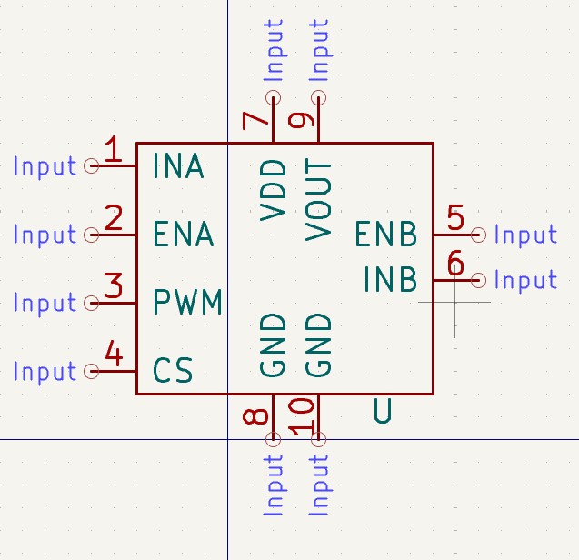
The schematic is the easiest, I just made a box with all the pin names on it.
For the footprint, I made a rectangle with the right dimensions in the top silkscreen to illustrate where the driver would sit. Then I used a pinheader, slightly modified by adding two more pins as the longes one I could find was 8. I just changed the pad numbers and verified they were on the right distance from each other and also the edge of the rectangle I had just created. Behold.
With the schematic symbol and footprint linked, I got to work making the schematic. Using the driver information, I surmised that CS - current sense- is a pin that can be read as an analog signal to indicate current. INA and INB indicate rotation direction, and because I did not have enough pins and I knew they should always be opposites, I did an inverse logic with an N channel MOSFET. When the signal from INA is up, then INB would be down. The PWM can be from any digital pin. And finally, I wanted a screen to be able to monitor the motors. For that, I used a OLED Display 128 x 32. This communicate sin I2C, so I needed the DA and SCL pins free. This left me with three pins available, so I added switches to be able to navigate the display and change speeds.
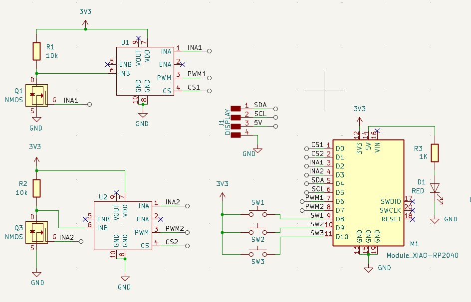
For easier debugging, I added several LED indicators to the pins from the digital signals and the buttons. This would make it easier to tell if it was up/down without needing to be driven by the program logic. Since I had no more pins, it was the only way I'd have visual indication, other than serial printing in the monitor.
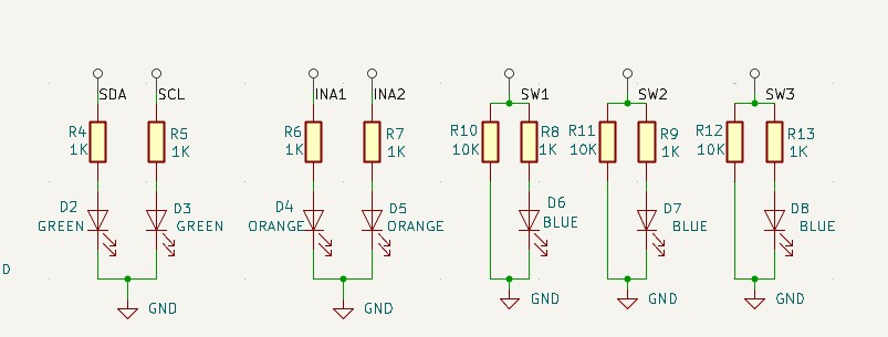
This is me forshadowing an error. Notice how the SDA and SCL pins are not pulled up, as they should be. This means the communication with the display is impossible.
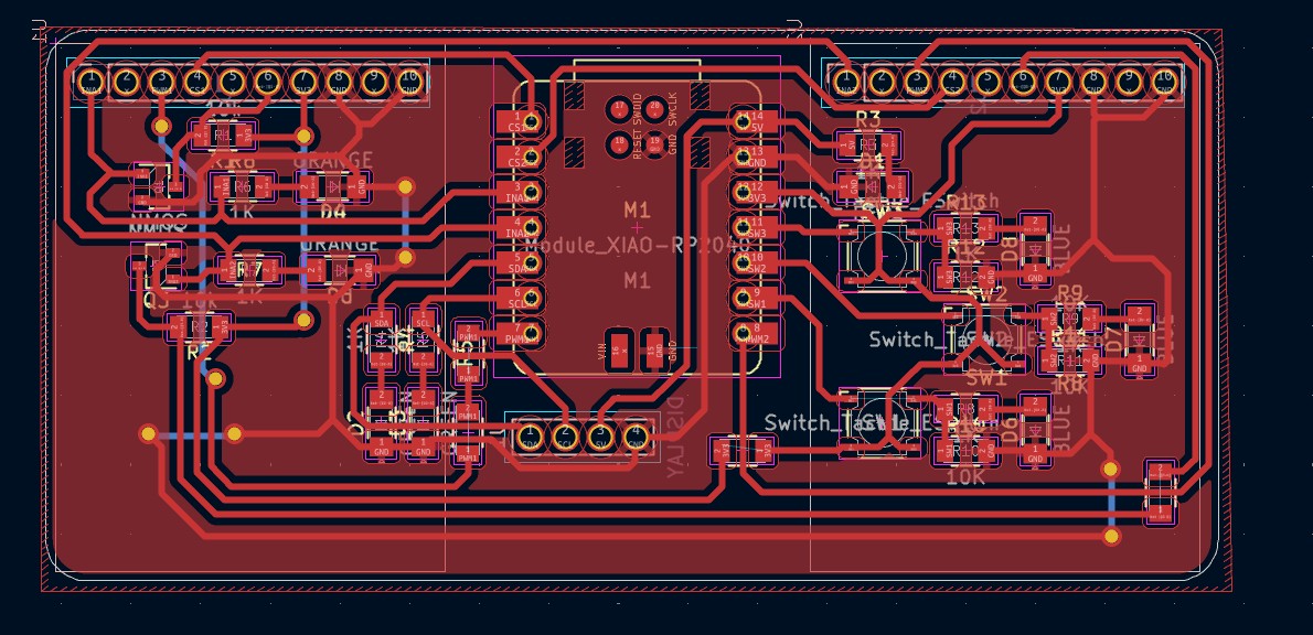
After getting ths schematic in order, I went to work with routing. I fiddled with the position and flipped the drivers to the bottom layer. I knew I wanted to mount them under the board so it was more compact and I could still put the LEDs in the same area (but on the other side, if that makes sense). In the end, I couldnt figure out the routing in a single layer with 0 ohm resistor jumpers, so I used routing on the bottom layer. In reality, I would be soldering wires on the underside.
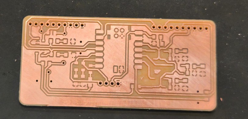
I used GBR2PNG to get my files for machining, went to the Carvera, and made the board.
.png)
I needed to do some cleanup in some traces that had little bridges and some that didn't get cut, but it was all solved with a box cutter. Filed the edges, sanded the board, and ready for action.
The BOM is as follows:
Also needed, but not on the board directly:
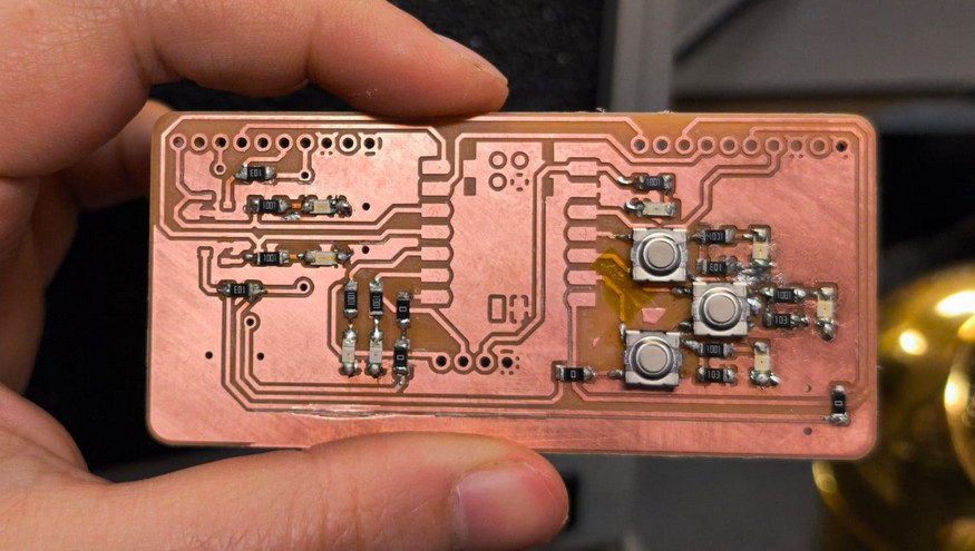
Little by little I soldered all the components, checking as I go that there are no shorts or bridges where tehy shouldn't be.
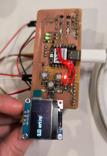
Look at it, so beautiful. If only it had stayed this way.Once all soldered up, I went in to the code to get it to do the things I wanted it to do.
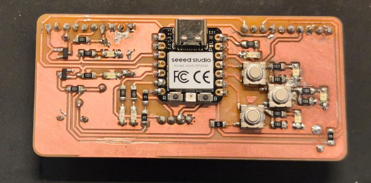
I first ran an example code for the Display. Here is when I noticed the display does not work. Going back, I realized I forgot the pull up resistors for the SDA and SCL. This required some surgery- I found a 3V3 line where I could solder the resistors, and cut up the ground plane around it to have space to wire a made up SDA and SCL pad. It was awful and timeconsuming and it looks very not pretty. Ideally, I would have machined another board, but there were other people using the machine and sodlering the entire board again would take much longer, or so I keep telling myself. The janky solution worked! So the OLED is runnnig, the buttons are pushing, and now on to using the H bridges.
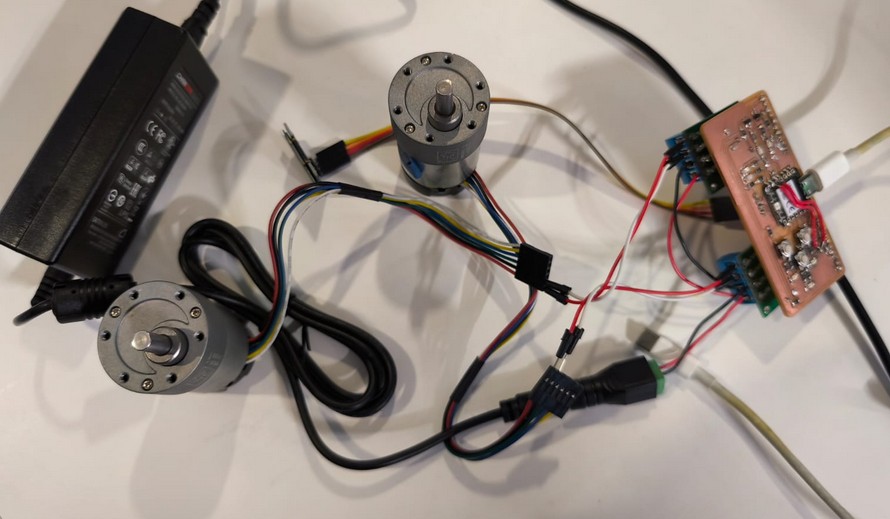
I wired up the motors, added their 12V input, and it was all looking beautiful, ready to go.
Coding is time consuming, so I asked for assistance from our favorite artificial intelligence. You know the one. (ChatGPT in case you don't)
My prompt was very specific, since I knew that I wanted. I hoped this would just work magically (it didn't). I usually code block by block, even when vibe coding- just adding a function at a time and checking as I go. But I am running out of time, I figured chat can handle all of it. So this is the prompt I did: Make a code for programming xiao rp2040 with arduino IDE and two pololu VNH5019 (ref: https://www.pololu.com/product/1451/resources). Driver A has connected: CS pin to D0, INA pin to D2, and PWM signal from D6. Driver B has connected the CS to D1, INA to D3, and PWM to D7. There is a OLED display connected with resolution 128 x 32 on I2C, with the address 0x3C, and is default (SDA connected to d4 and SCL connected to pin d5). There are three pushbuttons in pulldown, one going to D8, the other to D9, and the last to D10. The program should control the two motors, A and B. The display shows a menu in which the speed and direction of the motors can be modified separately. Button D10 should be up, and D8 down, and D9 is select. The first menu shows the two motor options and a "stop" option. The stop when selected makes both motors stop spinning. When selecting one of the motors, it will go into a sub menu that has speed,rotation, stop and return. When speed is selected, the up and down buttons change the speed. When rotation is selected, it will toggle CW and CCW. Stop stops only this motor. Return goes back to the main Menu. At all times, there would be a bar in the bottom that shows the current state of the motors. If up and down are pressed simultaneously for 1.5 seconds, this is ESTOP and the motors should stop spinning and the screen should say emergency stop. If they are pressed again, it returns to the main menu.
Alas, the first code generated did not even compile. I went through it fixing weird choices it had made, like establishing classes with 4 attributes and then assigning them 5 things. Very unconfident on this code. Still, once I managed to compile it, I uploaded it, and it bricked the Xiao LOL. The reboot works but i can't upload any code on it. Will update this site as soon as I get it fixed. Another mistake I did was recycling the schematic from the last week without fixing the pull ups for the I2C. So the display still does not work.
A reboot or two and an upload fixed it! The working code is here.
TODO insert video of working motors
I used the same board on my final project, please check that page for more details on the final implementation.