Week 12: Networks and Communications
This week I worked on the communication protocol I'd need for my final project. Since I'm going to be stacking blocks on top of each other, there'll be contact but I need to send information down (what blocks and in what order they're stacked) from the top to the bottom. Through talking with Anthony and JD, it seems like a simple tx/rx UART connection with attiny1614 microcontrollers in each block would be a good solution. I can use the grid's ground and VCC and send alternating TX/RX signals.
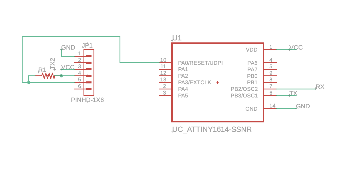
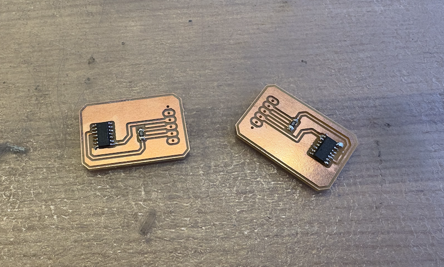
Here, we allow a serial connection to program the microcontroller by connecting the TX pin to a resistor (4.2 or 4.9K ohms) and combining with the RX pin to the PA0 pin on the attiny1614. Then, to connect a board to each other, I'd connect TX to RX and vice versa.
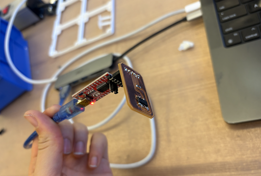
To be able to program the board, I needed to set some simple things up on the IDE. I installed the megaTinyCore packages and added board info with this link. The board is a megaTinyCore board with the attiny1614 microcontroller.
#define DEVICE_ID 0x04  // change per device

void setup() {
    Serial.begin(115200, SERIAL_8E2);
    delay(100);
}

void loop() {
    // forward everything from upstream first
    // while (Serial.available()) {
    //   Serial.write(Serial.read());
    // }

    // then append our id
    Serial.write(DEVICE_ID);

    delay(100);  // ~100hz
}
I as able to read the message the microcontroller sent by connecting the TX pin to a resistor (4.2 or 4.9K ohms) and combining with the RX pin to the PA0 pin on the attiny1614. Then, to connect a board to each other, I'd connect TX to RX and vice versa. To read it you can connect it to an oscillator and read the signal. I made the mistake of not using an LED or something to actually physically show if communnication was happening, but I did end up changing this for my final project work.