Week 8: Input Devices
This week is a combination of some of the previous weeks' topics, so not too much that is new. Last week, the board that I had soldered and made didn't work — never turned out, and I realize it was because of a mix of not testing if my solder didn't cause a short and not having a good enough connection to the board. You can look at the original design in Week 6.
IR Phototransistor
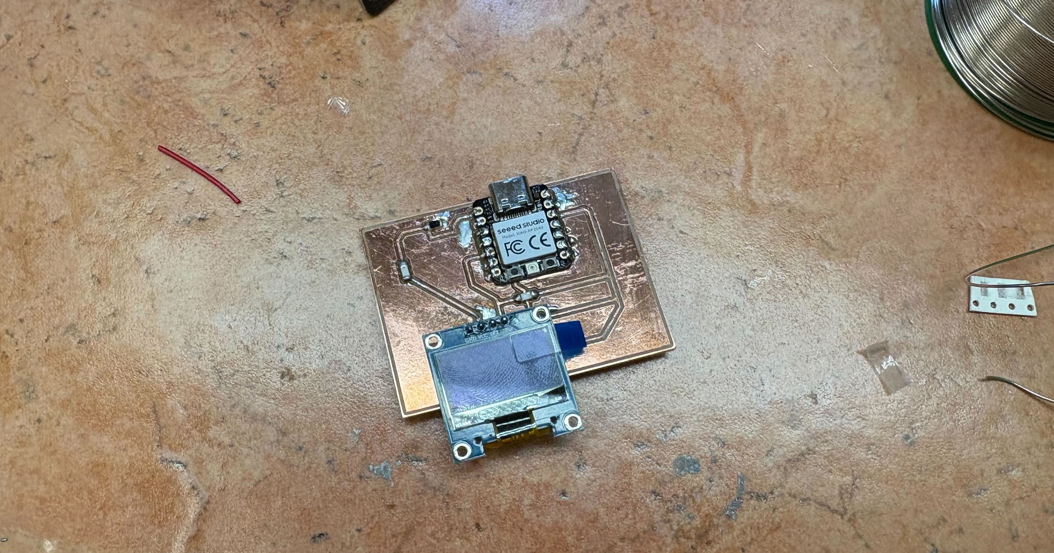
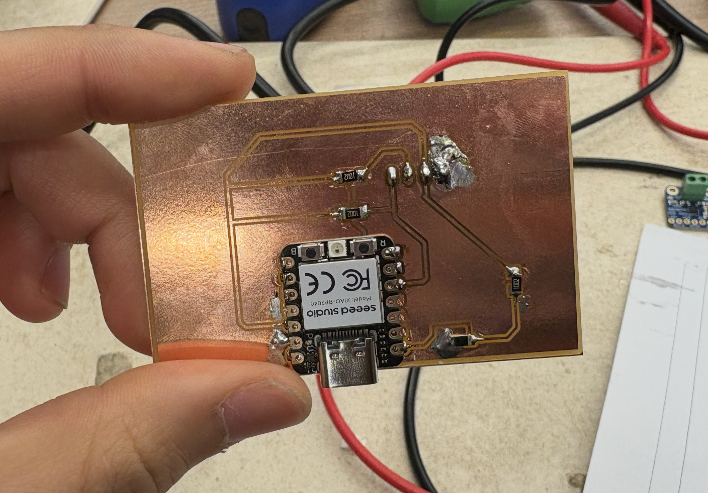
This week, I stuck with the same pads design but did some more research on the phototransistor and fixed the soldering.
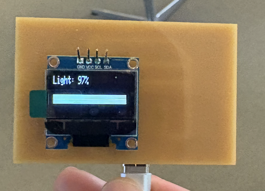
Then, I flashed a simple program to take in the data from the phototransistor and display it on the OLED display.
#include
#include
#include

#define SCREEN_WIDTH 128
#define SCREEN_HEIGHT 32
#define OLED_RESET -1

Adafruit_SSD1306 display(SCREEN_WIDTH, SCREEN_HEIGHT, &Wire, OLED_RESET);

const int PHOTO_PIN = A0;  // P26_A0_D0

void setup() {
    pinMode(PHOTO_PIN, INPUT);

    Wire.setSDA(6);  // P6_D4_SDA
    Wire.setSCL(7);  // P7_D5_SCL
    Wire.begin();

    if(!display.begin(SSD1306_SWITCHCAPVCC, 0x3C)) {
    while(1);
    }

    display.clearDisplay();
    display.setTextSize(1);
    display.setTextColor(SSD1306_WHITE);
    display.display();
}

void loop() {
    int raw = analogRead(PHOTO_PIN);
    int light = map(raw, 0, 4095, 0, 100);  // 12-bit range

    display.clearDisplay();

    display.setCursor(0, 0);
    display.print("Light: ");
    display.print(light);
    display.print("%");

    // debug - add raw value
    display.setCursor(0, 8);
    display.print("Raw: ");
    display.print(raw);

    int barWidth = map(light, 0, 100, 0, SCREEN_WIDTH);
    display.fillRect(0, 24, barWidth, 8, SSD1306_WHITE);

    display.display();
    delay(100);
}
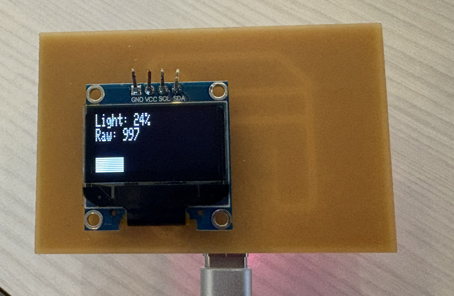
It turns out I had a slight misunderstanding of the Q phototransistor NPN I was working with. It's an IR sensor (not visible light), so the ambient light doesn't really affect it (and covering it doesn't change too much). Using a 10k resistor as a scaling resistor is good, but if I want it to be a bit more sensitive to small changes I can use a higher-value resistor.