Additive Path Planning
Additive manufacturing toolpath computation is considerably simpler than subtractive manufacturing because the problem can be reduced from 3D to 2D. The additive toolpath is made up of 2D layers (or “slices”) which are joined to produce a 3D object. However, it is complicated by the orientation of the layers, which depend on gravity to account for overhangs and material stresses. Additional heuristics can be added to toolpath generation to optimize on other machining constraints, such as build time, surface finish, and material consumption.
Additive manufacturing CAM workflow typically follows these steps:
- verify that the input geometry meets fabrication requirements
- determine the optimal orientation for building
- Assess need for additional build structures to be added to the geometry
- Slice the object (planar vs nonplanar, constant vs adaptive)
- Export machine instructions (vector based vs raster based path)
Geometry requirements
Determining wether or not a 3D printer can print a geometry is a complex decision which depends heavily on the local thickness of an input geometry. If certain areas of the input mesh are too thin, they must with offset or thickened.
Rolland-Neviere, et. al. provide a sampling algorithm for robust thickness estimation that can hold up against common mesh artifacts.
Wang and Chen developed an algorithm to automatically thicken CAD/CAM surfaces. Note the difference between thickening and offset.
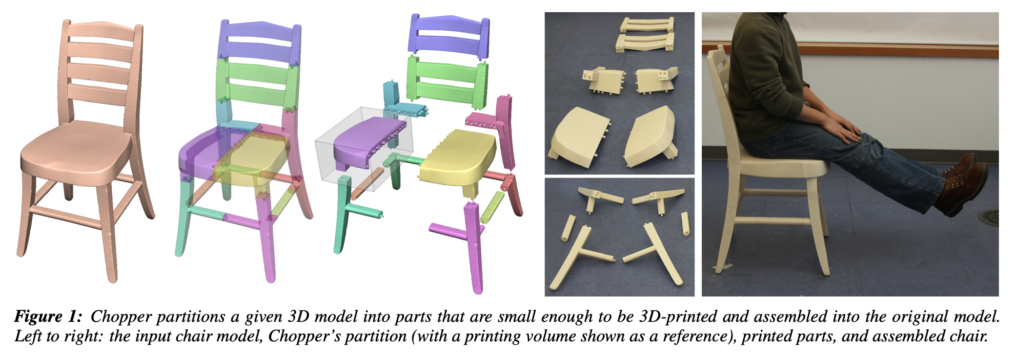
Luo, et. al proposes a framework called the “Chopper” which can decompose large 3D objects into smaller parts to fit into a given printing volume. The Chopper can automatically (or with user guidance) optimize parts for ease of assembly, minimal part count, structural soundness, and unobtrusive seams.
Mesh Repair
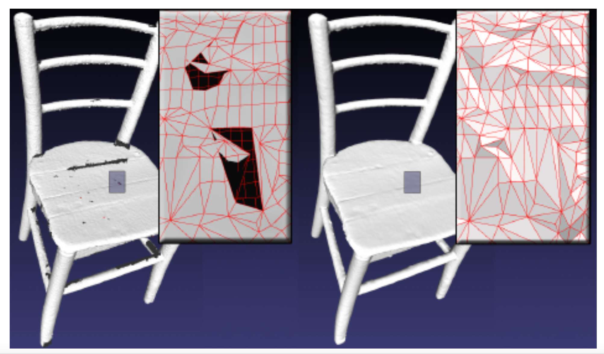
Slicers must receive a watertight mesh as input, meaning that all non-manifold structures and holes must be removed. It can also be useful to reduce the complexity of meshes by decimating triangulated surfaces while preserving geometric detail or resampling meshes to increase the number of triangles. Specifically, 3D scanned models typically output incredibly messy meshes which are fine for observation, but upon closer inspection have overlapping parts, surface holes, or self-intersections.
Formlabs provides a rather indepth blog post on repairing 3D models in an STL file - here. It includes quickstart guides on how to use five different free mesh repair softwares: Meshmixer, Meshlab, Magics, Blender, and Netfabb
Attene developed a lightweight mesh-repair algorithm which only modifies the mesh in the neighborhood of unwanted features, instead of completely resampling and remeshing. This seems to be the founding paper around simple, localized mesh repair. He also maintains a list of open source mesh repair tools here.
Slicing
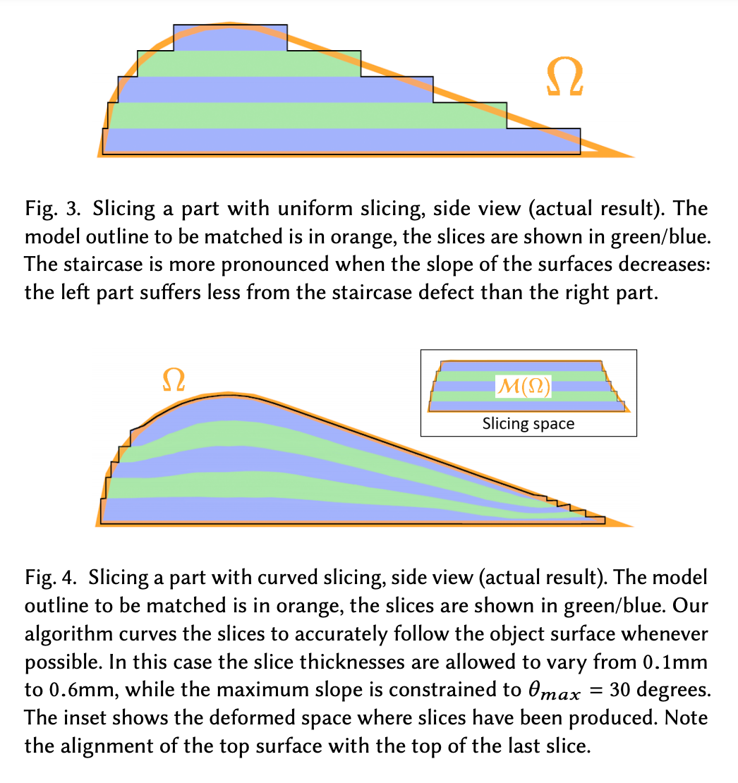
Once a sufficient mesh is created, the structure is “sliced” from a volume to a plane. Traditionally, the volume is sliced along horizontal parallel lines with the thickness between each slice determining the surface finish of the final print - referred to as “planar slicing” or “flat layer slicing”. The slicer must determine the vertical position of each slice, efficiently compute the contour within each slice, and then fill that contour with a toolpath. The slicing can be done uniformly or adaptively.
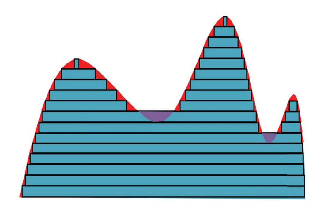
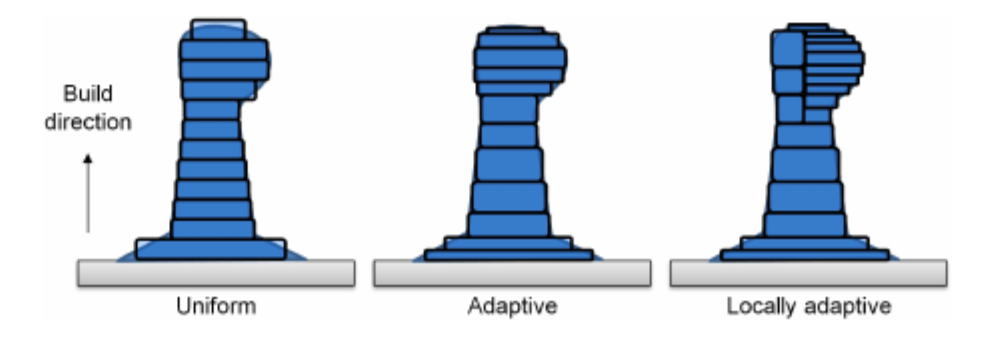
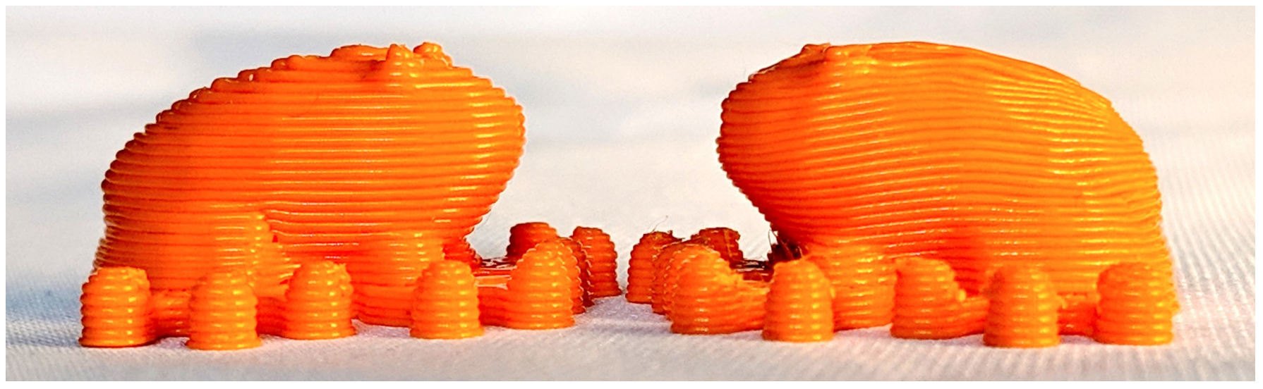
- uniform slicing: Given a manufacturing layer thickness t, and object height, h, the object is divided into N=h/t slices and each slice i is located at height \(z_{i}=\frac{i+0.5}{N}\). This guarantees uniform slice distance across the whole object. This is fine for object with vertical walls, but will result surface errors due to the “staircase effect” - as shown highlighted in red error below.
- adaptive slicing: Since most manufacturing technologies have some control over layer height, an adaptive slicing approach can be used which modifies layer thickness based on the curvature of the volume at that height. More complex implementations also exist to change the layer height only on sections of the object which require it - i.e. local adaptive slicing. However, local adaptive slicing can also be difficult because it creates seams along the solid where disjoint layers need to recombine.
More recently, non-planar slicing (aka curved-layer printing) has become popular for printers which have an extra rotating axis to extrude along angled or curved surfaces. The comparison between planar and non-planar slicing was covered in last week’s Material Extrusion section. Quick review: at the expense of more complex computation, non-planar extrusion leads to better surface quality, optimized printing time, better self-support, and improved tensile strength.
it’s quite trendy, so additional info on non-planar printing can also be found:
- here - A Grasshopper Rhino extension developed for curved-layer printing of large-scale construction components
- and here - CurviSlicer bypasses computing curved layers directly by first transforming the model to be more flat, slice the object with the standard planar approach, then recovering the object’s initial curvature
Support Structures
Support structures can be added to compensate for limitations in local depositions due to gravity, structural strain caused by material imbalance in either deposition or solidification processes, or thermal dissipation in metal printing.
Determining support placement requires detection of islands and/or overhangs and then generation of proper support geometry. Support construction is an important step to optimize due to the excess build time, material waste, and post processing that they introduce.
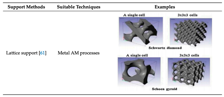
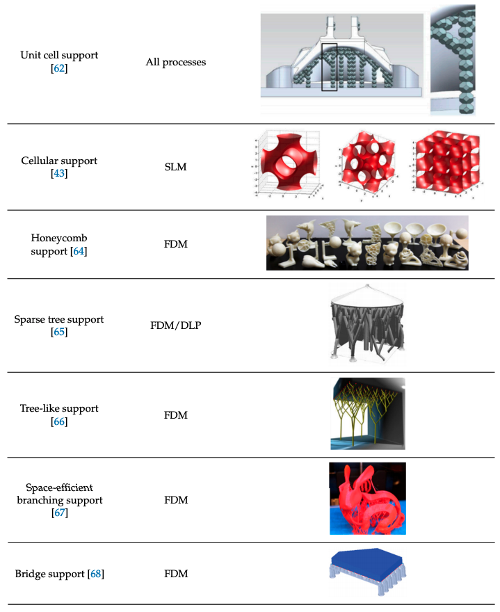
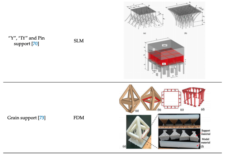
Optimized support structures are a growing area of research as additive manufacturing becomes more prevalent in industrial processes. Jiang et. al.’s 2018 review paper on support structures for additive manufacturing provides a clear comparison between different methods matched to process techniques.
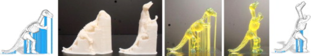
Another interesting approach minimizes supports by perturbing the original model’s angles and feature shapes to maximize self-stability, referred to as an “orientation-driven shape optimizer”. Hu, Jin, Wang (2015)
Infill (aka internal supports)
The internal supports of a printed object has significant impact on build time, material use, and structural stability.
Dense infill
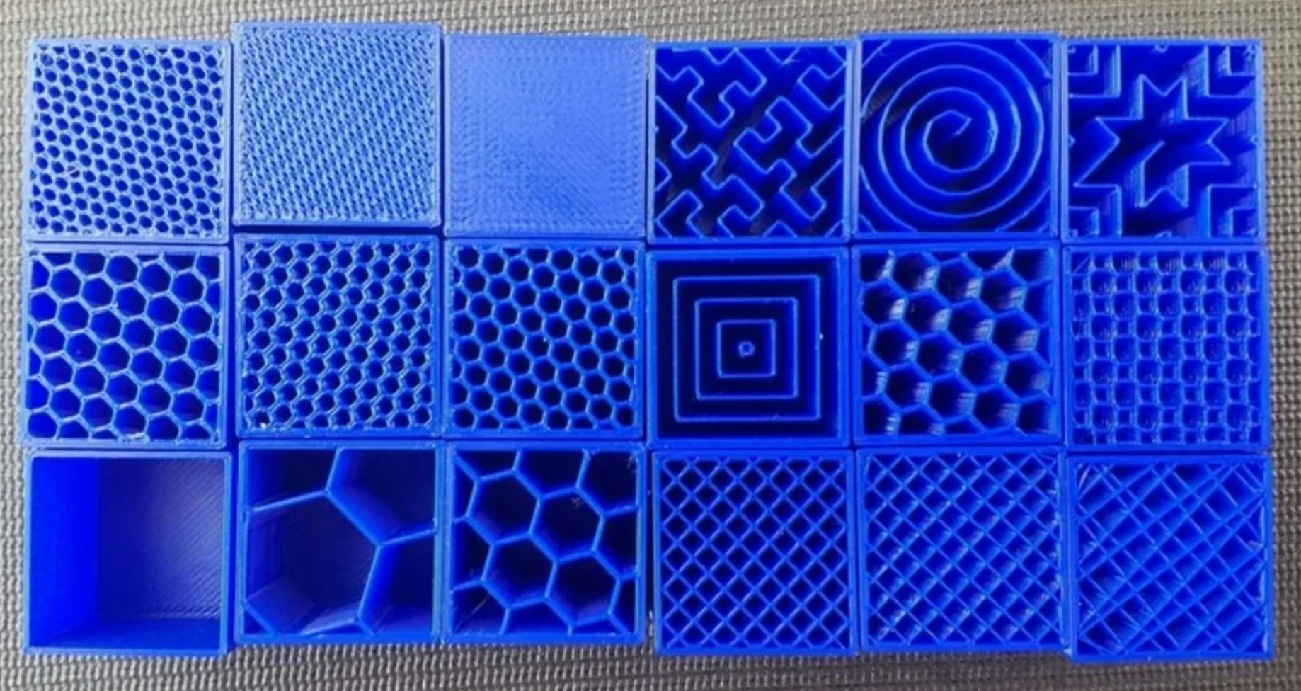
Common infill patterns: 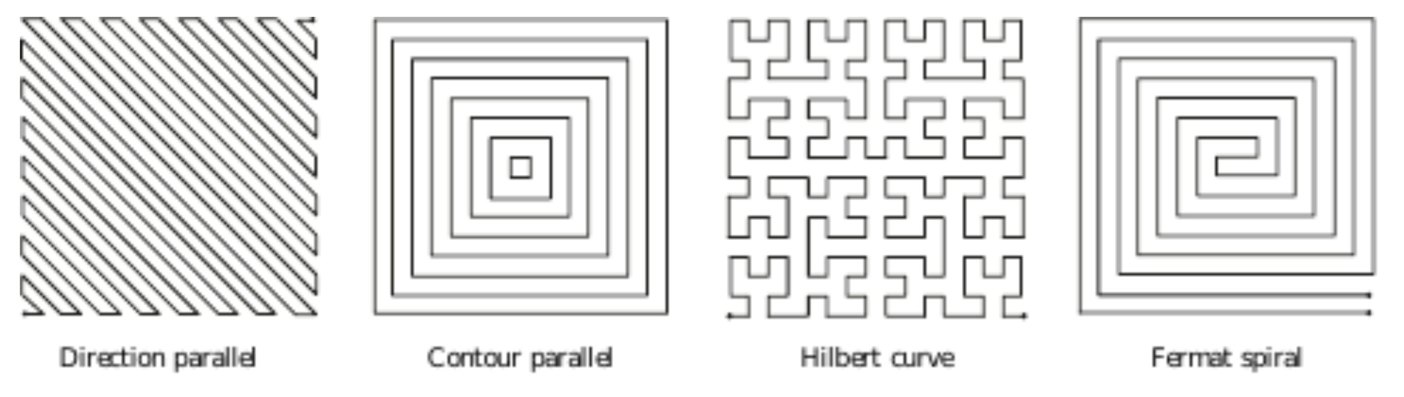
Direction parallel: (aka zig-zag) fill a slice area with equally spaced parallel line segments. The density of the fill can be determined by the spacing between these segments and the direction of the parallel lines change every two slices so that mechanical bias does build up. However, there are a lot of sharp corners in this fill, which makes complex shapes or hollow structures difficult and adds unnecessary de-acceleration and acceleration times for an extruder toolhead.
Contour parallel: paths are defined by iso-contours of the euclidean distance transform, aka concentric closed curve offset stepping in from the outer boundary with equal step sizes. However, iso-contours are disconnected from each other, which can lead to difficult gaps. Sometimes a mix of a few contour curves and then zig-zag fills will be used, but again care must be given for gapping structures.
Hilbert curve: is a space filling curve which is designed to wind and bend itself to preserve locality as it travels through a space. This is a classic space filling curve used in some manufacturing, although it’s not the best choice for infill because of the constant sharp turns that it’s defined to take.
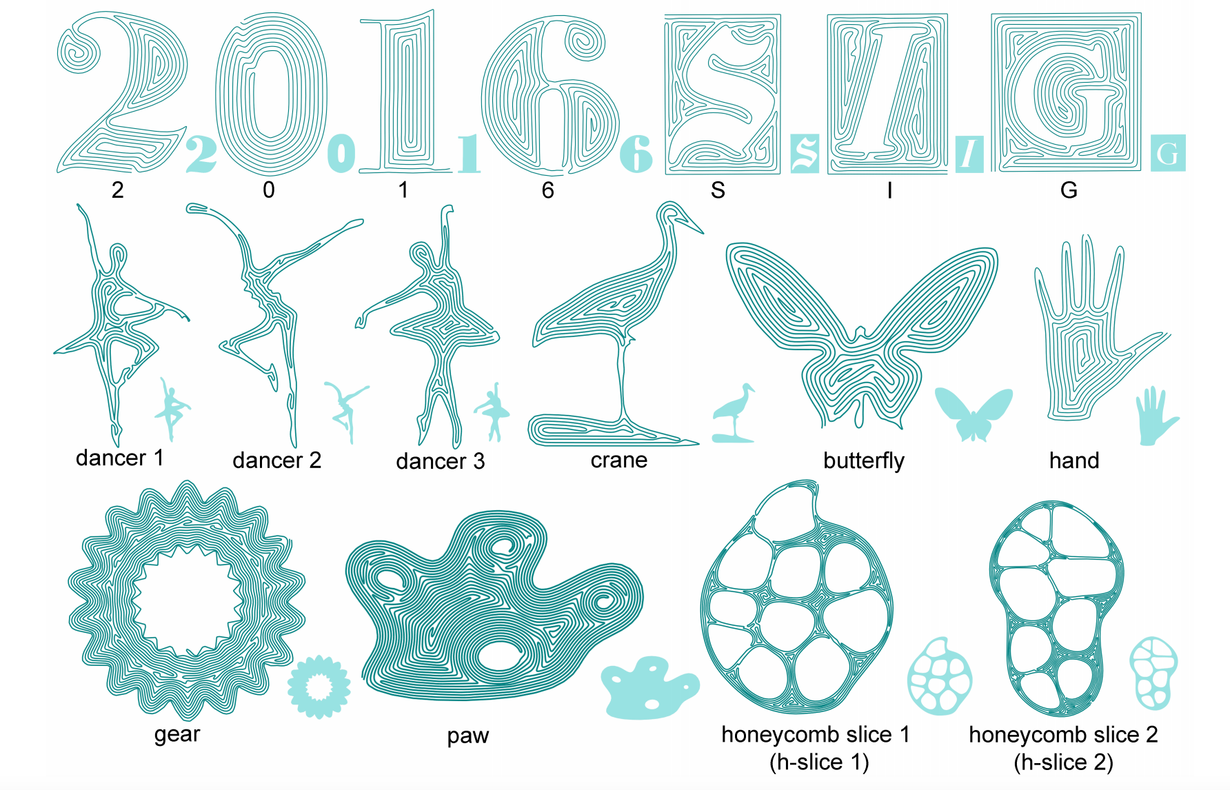
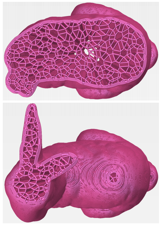
Fermat Spirals: are a type of space-filling curve that is designed to avoid bending - although it’s not guaranteed to cover an entire 2D space, even at infinite resolution. Fermat spirals are similar to contour parallel paths in that they conform to the region boundary. They are also beneficial because they can have arbitrary start and end points and continuous connections, allowing a curve to spiral both in and out as opposed to one or the other. However, spirals can be suboptimal filling patterns due to their lack of direction bias, which prevents cross woven slices for mechanical uniformity. See Zhao, et. al. for more on Fermat spirals shown below.
Tessellations
Infills that do not care about dense space filling can be designed using any type of space-filling tessellations, such as honeycomb, or rhombic
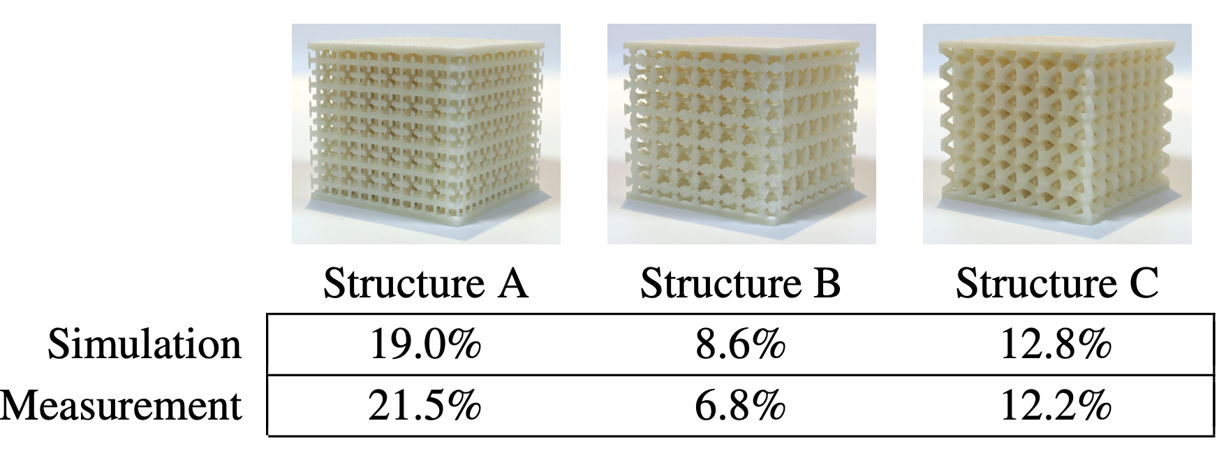
Metamaterials
These can be optimized to use as little material as possible while maintaining structural strength. Furthermore, internal microstructures used to create metamaterials that have pre-defined control over elasticity, as demonstrated by Schumacher et. al.
Continuous Toolpathing
This year, Gupta et. al. developed a new framework for continuous toolpathing for sparse infill additive manufacturing. This algorithm draws a continuous path with no crossovers for each contour slice - this ensures greater print yield quality because of the lack of start and end points on each layer and uniform thickness of each contour. The heart of the framework is an euler transformation on the 2 cell complex K such that the 1-skeleton, G^, of the new 2-complex K^ has an even degree on each vertex; therefore G^ is eulerian and an eulerian tour can be followed for print each edge continuously without stops.
Non-conventional
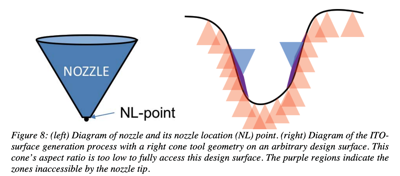
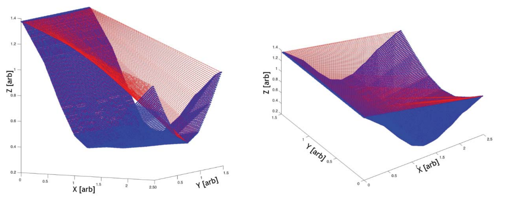
Fully three-dimensional point-based additive manufacturing throws away the concept of slicing for AM and generates a method for 2.5D toolpathing that is more similar to CNC milling, which it defines as “point-based additive manufacturing”. Like the cutter contact (CC) and cutter location (CL) points in subtractive milling used to generate an inverse tool offset (ITO), the additive equivalent is the nozzle location (NL) which can also be used to generate the ITO. Then, the ITO-surface can be evaluated for “printability” by not allowing surfaces with local magnitude of separation exceeds manufacturing tolerances. Shown below, this curve is unprintable because a surface with this steep of slope cannot be accessed by the nozzle with this cone aspect ratio - the problematic areas are highlighted in purple.
Once the curve is verified for printability, then the complex contours can be traced into g-code commands following algorithms familiar to 2.5D milling
This method significantly reduces volumetric fabrication error due to the lack of slicing, however steeps curves are difficult to produce and it’s impossible to have vertical build directions.
References
Most of the structure for this page is derived from: Lievsu et. al., From 3D models to 3D prints: an overview of the processing pipeline (2017).
Pandey et. al., Slicing procedures in layered manufacturing: a review, (2003) gives a review of slicing algorithms, although it’s a bit out of date since cutting edge slicers are now exploring curved layer printing.