Subtractive Path Planning
We’ll start with a review of material we covered during the subtractive manufacturing week. This page is more specifically written about milling metals than routing plastics or wood, but all the concepts apply to all these subtractive processes.
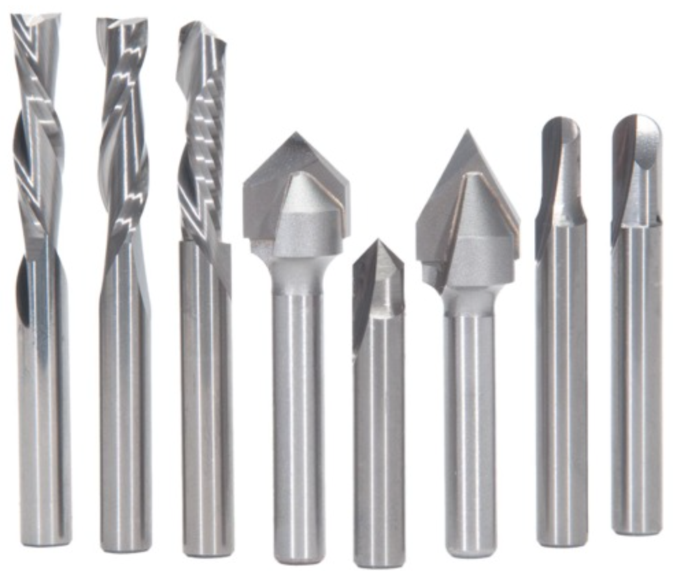
Tool Shapes
- Flat end: rectangular profile
- Bull nose: rounded rectangular profile
- Ball end: circular profile (at the tip)
- Conical/chamfer: conical tips, used for cutting angled surfaces (like chamfers) or engraving
- Specialty: various curvy shapes exist, as do specialized tools for tasks like tapping holes (i.e. adding threads)
Different tools have different cutting regions. Some should primarily be used to cut with their sides, others primarily with their ends or tips (like drill bits). Many offer a mix of both.
Cut Types
There are two main classes of cut: roughing cuts and finishing cuts. Roughing cuts are intended to remove bulk material quickly, while finishing cuts are intended to create smooth, dimensionally accurate surfaces that will be visible on the final part.
There are many different ways to use a tool to cut a surface.
- Side or swarf milling: use the side of a tool to mill a vertical wall (relative to the tool). On a five axis mill, you can create helical and other developable surfaces this way.
- Face milling: use the end of the tool (on a flat end or bull nose tool) to mill a planar surface.
- Interpolation: Use the rounded part of a ball end or bull nose tool to approximate an arbitrary surface with many closely spaced passes.
Generally speaking, for finishing cuts it’s preferable to use side or face milling over interpolation whenever possible, since interpolated surfaces take far longer to mill and will never be as smooth. Roughing cuts these days are usually done with trochoidal paths, which are primarily a side cutting technique.
Single Cut Path Planning
Given a tool, a surface to cut, and a reasonable cut type, there’s usually a fairly straightforward way to develop the path geometry.
Two essential concepts are step-over and step-down. The first is the thickness of material the tool cuts along a radial direction, and the second is the thickness of material the tool cuts along its axial direction. There’s a whole science/art to choosing step-over and step-down relative to your desired feedrate and chip load. Much of this we went over during subtractive week so we won’t go further into it here.
Zig-zag For facing large areas with no potential collisions, you can just go back and forth across the whole surface. The separation between adjacent lines is determined by your step-over.
Spiral Another strategy is to use a spiral instead of a zig zag path. Again the geometry is largely driven by the step-over.
Offset If we’re facing the bottom of a pocket (i.e an area with walls that we can’t crash into), it’s often helpful to use offset based paths. Offset paths are also what are used to finish vertical walls (with a side or swarf milling cut). These can be calculated using the offset algorithms we saw in the computational geometry section.
Adaptive Clearing/Trochoidal As we saw during subtractive week, a variety of specialized paths exist for roughing as quickly as possible. These often require specialized algorithms to compute. In particular, research papers are still regularly published with new strategies for trochoidal milling.
Swarf This is an offset path for a (developable) surface, as opposed to a curve. Offsets of planar, conical, and cylindrical faces can be determined analytically, while offsets of NURBS surfaces must be approximated with specialized algorithms. Here is a demo video of setting up swarf milling in MasterCAM.
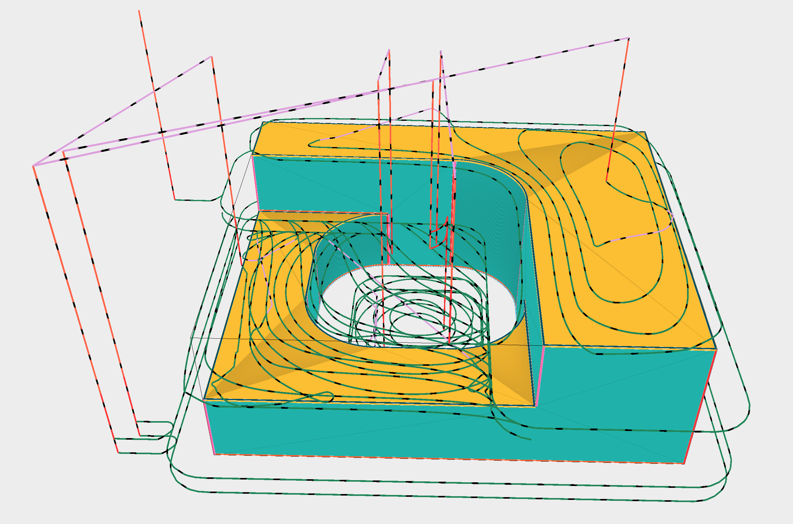
Here’s one of Jens’ images from subtractive week that demonstrates adaptive and zig-zag paths in a pocket. (The zig-zag path uses little segments of offset paths to connect the “zigs” with the “zags”.) It would be common to see a machinist use the adaptive path on the left for roughing operations, leaving some extra thickness behind on the walls and floor, then use the zig-zag path on the right to finish the floor, and an offset path to finish the walls.
Full Part Path Planning
When we start thinking about making the whole part, instead of just one cut, things get a lot more complicated. Now we have decisions to make about which tools to use. Before that, though, we have to figure out how to hold the part.
Workholding
Milling generates large forces on the part and tool, so we have to fasten it to the machine very securely. For milling this is most often accomplished with a vice. For thinner or softer materials you can also use a vacuum bed. Both of these strategies only work for certain geometries: stock vice jaws require parallel planar faces on opposite ends of the part, and a vacuum bed requires a large flat face which will generate enough suction to hold the rest of the part with it. To get around this, it’s common to mill specialized vice jaws that conform to the shape of the part. Making these can be a pain when you’re prototyping since it requires additional milling operations and stock material. Finally, if your part has bolt holes or other attachment features, you can use those by milling a custom adaptor that attaches to your machine bed on one side, and your part on the other. Of course this only works once you’ve machined those holes in your part.
Workholding necessarily removes access to some regions of the part. So usually we have to plan multiple milling operations with a change (or more) of workholding part way through. Ensuring that the cuts from the different operations are aligned can be quite tricky. A lot of thought goes into providing repeatable kinematic positioning of the part within vice jaws, etc.
Choosing Tools and Cut Types
As we’re planning our workholding, we also have to decide which tools and cut types we want to use. In a part represented as a conventional CAD model, i.e. using a boundary representation made of stitched together planes, cylinders, cones, and NURBS, we can usually start by considering each face separately. Planar faces can be face milled or side milled. Cylindrical faces must be side milled (or interpolated). Conical faces can be cut with a chamfer tool, swarf milled, or interpolated (the usual last resort). NURBS faces, unless they happen to represent a simpler face type, in general need to be interpolated.
If we choose a tool for each face individually, though, we may end up with a program that has a lot of tools. This means more tool changes, which wastes time. Especially if we can’t fit all these tools in our tool changer at once (assuming we have one). Often machine shops have a standard set of tools that are always loaded, so it’s useful to rely on those as much as possible, to reduce the number of part specific tools that need to be swapped in before the program can be run.
Collision Avoidance
Finally, we get to one of the most important considerations. When we’re cutting one face, we don’t want to damage another. And we never want to start cutting into the machine itself. Collision detection is its own subfield of computational geometry, so there are many approaches to take. Usually we’re interested in detecting collisions between a mostly cylindrical object (the tool) with the surface of the part (usually a primitive based boundary representation), and the surface of the machine (which we generally have as a mesh rather than a CAD model). We’re also interested in the collision of the machine with itself (mesh to mesh).
To reduce the number of different algorithms we have to employ, it can be helpful to explode the machine and part into point clouds. Then tool collisions are reduced to checking if points fall inside cylinders. If the points are close enough together, we can make guarantees on the possible error introduced by this discretization.
Automation
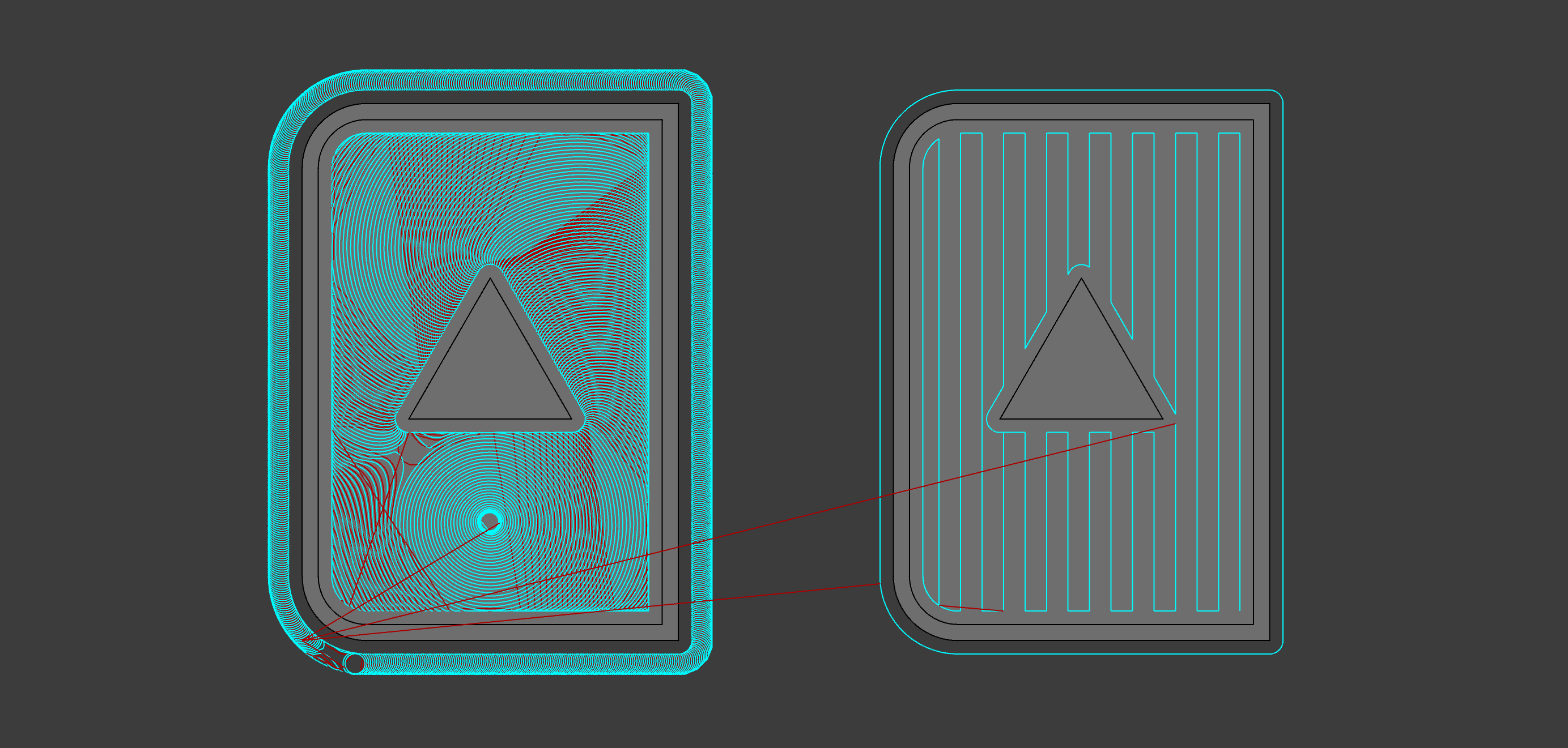
By putting all these pieces together, it’s possible to completely automate the CAM process. Various companies do this to varying degrees. Protolabs and Plethora do this as part of a manufacturing-as-a-service model. CAM packages are introducing more automation features as well, such as Autodesk’s FeatureCAM. The image below shows automatically generated toolpaths for a simple test part.