For a program to communicate remotely, I needed to learn how to use serial.available and serial.read, to read messages from the serial monitor.
The initial structure of the script comes from ChatGPT, which was helpful for some of the syntax, but included references to raspberry pi peripherals that I was not using.
After manually cleaning up the script, I was able to get what I want: the LED responds to text prompts from the user. Final code for this example can be found here.
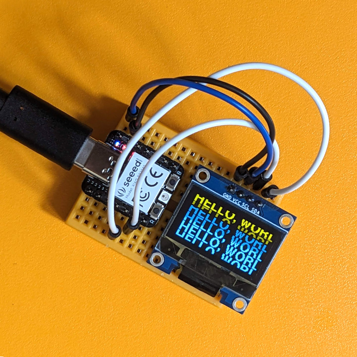 Typography graphic display using Grove 0.96" OLED peripheral.
Thinking toward the final project, I know that I need to learn more about interfacing different devices with the microcontroller. I chose a simple OLED display, and began researching how to use a breadboard and jumper wires.
My Arduino Sketch for this example was adapted from the Seeed Studio Wiki
To use the 0.96" OLED display, four wires are required. Connections are as follows:
XIAO GND == OLED GND
XIAO VCC == OLED VCC
XIAO Pin 4 == OLED SDA Pin
XIAO Pin 5 == OLED SCL Pin
4. Group Work
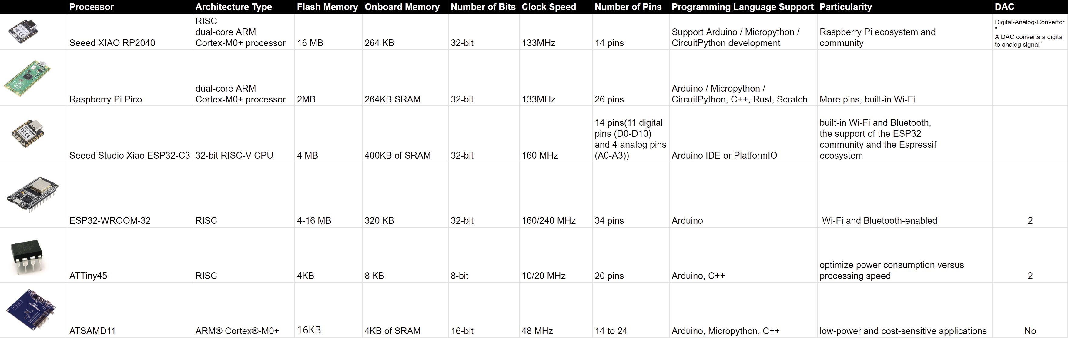 Working with Nasibe Nur Dundar Arifoglu, we assembled a table comparing some development characteristics of working with the different microcontrollers.
Each of the datasheets for these microcontrollers have such vast amounts of information, there isn't necessarily one intuitive way to organize the categories. Several times, we would think a category was necessary, only to realize it didn't apply to the other boards and wasn't a useful criteria. This finding especially applied to pin layouts and peripheral compatibility.
As we looked through the options, I started to appreciate how we might work backwards from our final project to fine-tune our processor selection depending on what we need: lots of pins, low cost, processing speed, etc.