


Because the ATTiny44 microcontroller we used this week doesn't have many pins, I thought it would be a good opportunity to learn to use a multiplexer. I also wanted to use interrupts. I've never worked with microcontrollers outside of the Arduino environment, and one thing I was excited about this week was to learn finer control over the timing of a running program.
The board I decided to make is an electronic die. The microcontroller sends signals to a demultiplexer, cycling through 6 outputs that go to LEDS. When the user hits the button, the cycling is stopped, and the output that was selected lights the LED connected to it.
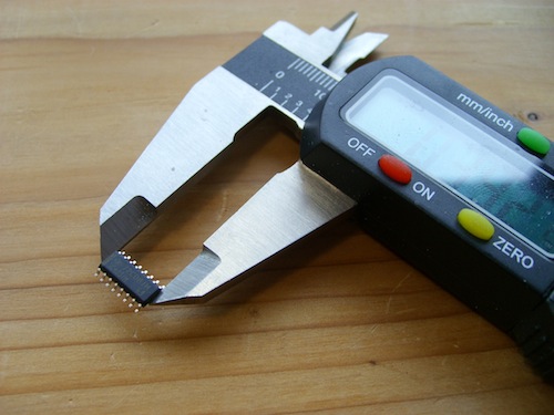
In order to add a demultiplexer, I needed to create a soldering footprint for it to add to the board. The datasheet specified "SOIC 16," but (at least according to Wikipedia), this simply means "small outline integrated circuit" and doesn't guarantee the size.
My initial approach, before realizing there was a better way:
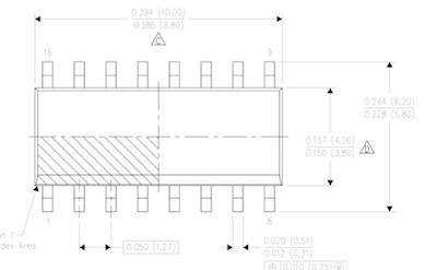
I then realized the datasheet specifies a footprint:
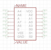
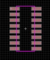
I followed this tutorial from Sparkfun to create a custom part in Eagle (great tutorial except for the slightly annoying fact that the commands were all specified as Windows shortcuts).
A lovely custom part and footprint ensued:
...and then things got crazy.
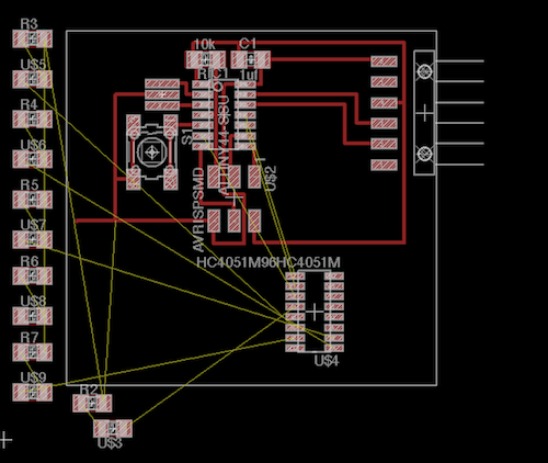
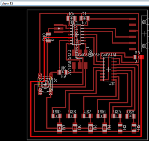
I had no idea that the routing was going to be the most difficult part in all this. I'm not even going to go into how long this took, but adding another component and a bunch of LEDs is a lot harder than it might appear. The problem was that I only had four free pins on the ATTiny44, on different sides of the chip, and that I had to route to four different pins on the demux, also on different sides on the chip. I tried to shuffle around just about every pin on the microcontroller, only to discover from the datasheets that most of them were dedicated to particular functions (for instance listening to clock signals). Finally I realized I could go underneath components, and was reminded that I could use 0 ohm resistors to jump over traces. It still turned out rather messy, for example where this signal pin had to go:
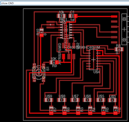
Or ground:
I also realized partway through routing that I didn't have an input to the demux and had run out of microcontroller pins. The solution I came up with to this was to use the same line as the pushbutton output, which would also implement part of the code directly in hardware: an LED would only be able to light up when the pushbutton was pressed. For this to work I had to use an external pull down resistor instead of the internal pull up resistor on the button pin (side note: the programming session this week was the first time the idea of internal pull up resistors "clicked" for me...hooray!)
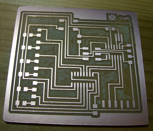
But at last it was done, and milled on the Mantis (yay):
And carefully stuffed:
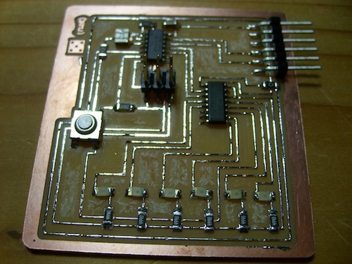
The program in action:
Lessons learned: It turns out I could have reused the MISO, MOSI, SCK pins (because they're only used when programming) and had 6 LEDs total controlled without a demux. I'm not too unhappy about this because part of the goal of this was to learn how to use a demux, but next time I will know. Also, since I'm only lighting one LED at a time, I could have used just one resistor instead of 6.
(Under Construction) Press the virtual pushbutton to remotely roll the die!
