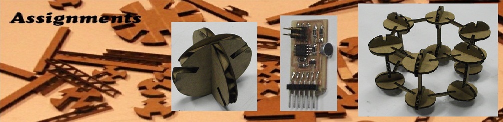

Assignments
Embedded Programing
I programmed my Hello world Board using many different enviroment (Terminal, Eclipse IDE, AVR Studio).
Tutorial on each of them is documented below.
Setting Up Ubuntu
You need following package for setting up your ubuntu of AVR programing
1. gcc-avr The GNU c compiler for AVR
2. avr-libc C library for AVR
3. binutils-avr - The name GNU Binutils stands for "Binary Utilities".
Below is a list of the programs that are included in Binutils:
(a) avr-as The Assembler.
(b) avr-ld The Linker.
(c) avr-ar Create, modify, and extract from libraries (archives).
(d) avr-ranlib Generate index to library (archive) contents.
(e) avr-objcopy Copy and translate object files to different formats.
(f) avr-objdump Display information from object files including disassembly.
(g) avr-size List section sizes and total size.
(h) avr-nm List symbols from object files.
(i) avr-strings List printable strings from files.
(j) avr-strip Discard symbols from files.
(k) avr-readelf Display the contents of ELF format files.
(l) avr-addr2line Convert addresses to file and line.
(m) avr-c++filt Filter to demangle encoded C++ symbols.
4. gavrasm - A command line assemble
5. AVRDUDE - program to writes data on the microcontroller)
6. avr-gdb The GNU debugger for AVR. This program runs from the
terminal avr-gdb, avr-gdbtui, avr-run
All of the above software can be installed using Ubuntu Software
Center, by simply searching and installing from the list.
Eclipse IDE
1) Downlaod Eclipse fro C/C++ developers as shown below ( http://www.eclipse.org/downloads/?osType=linux ) (also install avrdude)
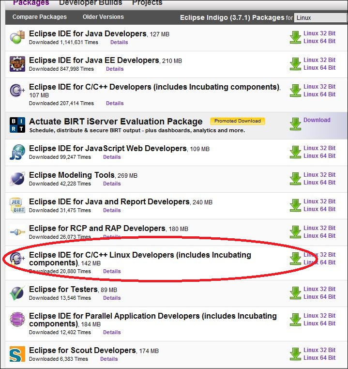
Extract the files, navigate to the ~/eclipse folder and double click the elipse file. If it displays the error that no JRE in your system, then run the command in terminal - sudo apt-get install default-jre . Once done you should be able to run the eclipse IDE.
2) Now close the Eclipse UDE and downlaod the AVR Eclipse plugin , from http://avr-eclipse.sourceforge.net/. Extract the files. Copy the folders inside the "features" folder in pluging folder to the "feature" subfolder in then the eclipse directory. Do the similar copying for folders inside plugins directory to the plugin subfolder of eclipse direcotry. It should shown "AVR GCC Toolchain", If not plugin is missing.
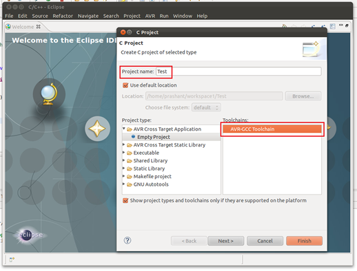
3) Click Next "Select Configurations" window will appear. Again Click Next "AVR Target Hardware Properties" window will appear. Select your MCU type and MCU frequency and Click on "Finish"
4) Close the Welcome window and behind that you will see the "Project Explorer"
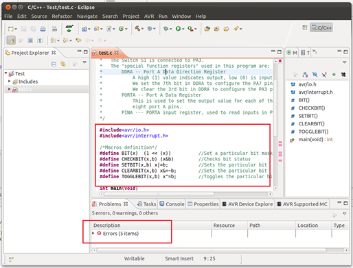
5) G to New-> C source -> and save it. Write your code in this file.
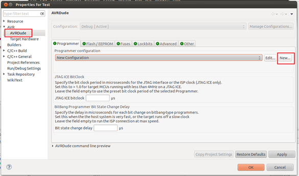
6) To select programmer go to Project -> Properties -> AVR -> avrdude and edit the settings for your programmer (I used AVRISPmkII and for port -P I set USB
6) To uplaod your code into the micro-controller go to AVR-> Upload Project to Target Device
AVR Studio
Setting up your computer -
1) Install AVR studio 5 ( http://www.atmel.com/microsite/avr_studio_5/default.asp?source=redirect ).
2) For programming, I am using AVRISPmkII ( http://store.atmel.com/PartDetail.aspx?q=p:10500054 ). Make sure to power your board from external power supply (USB port etc.)
Steps
1) Go To File -> New -> C Executable Project (Write name of your project, browse for location). Click OK.
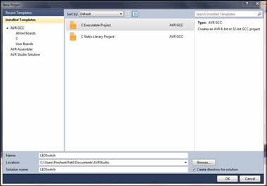
2) In the Device Selection window select your microcontroller. (In my case it is Attiny44A)
3) AVR studio will open up a .c file with some initial code. You can write you code in this file. Once finished writing the code, Go to Build - > Build<filename> or simple click the Build button shown below.
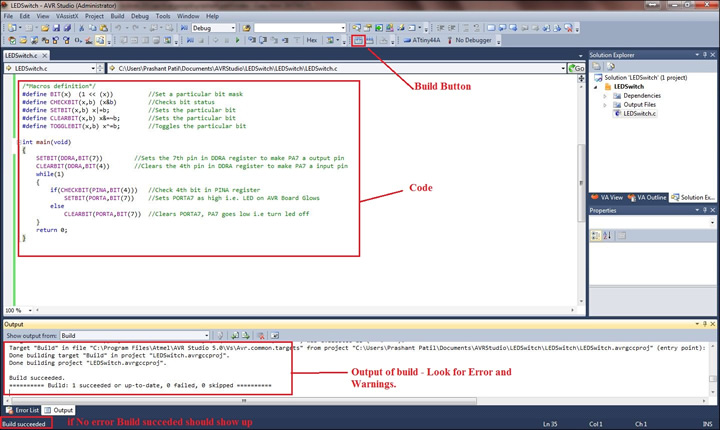
4) The program will compile your code and if no error you should se Build:1 succeded at the Output window as shown above. A <filename>.hex file will be created in the project directory which we have to upload to the micro-controller.
Different combination of above building blocks can be used to build the unit cells of all the crystal structures. Here, I have shown few examples -
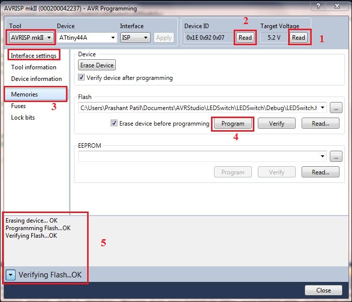
Step 5: Programing the board - Connect the ISP pin of AVRISPmkII to your board (make sure you connect in right polarity). Go to Tools -> AVR programming. In the "Tool" drop-down list select your programmer (I used AVRISP mkII), In Device select your uC ( I used ATtiny44A). Click on "Read" button below Target Voltage, the reading should be the voltage you are supplying to your board (Use external power supply to power your board, AVRISP mkII do not power the board unlike FabISP). Similarly click on "Read" button below Device ID and your device ID should appear provided all the connections are correct.
Debugging - If something goes wrong, check your connections and try varrying ISP clock speed in the "Interface Settings" Tab.
Step 5: For programing go to "Memories" Tab, browse to the projectfolder/Debug and locate the filename.hex file, then click on "Program" button. If programmed The message at the botton should read like " Programming Flash OK" as shown below.
Step 6: Immidiately after the programing finished, the board will start executing the code and we can use the board.
Code
1) Blink LED
/* blinking_led.c
*
* This code blinks the LED D2 on PORTB PIN6 i.e PA7 of the AVR board.
*
* The LED D2 is connected to PA7 on the Atmel chip, and is wired so that
* it will be ON when the output is high and OFF when the output is low.
*
* The "special function registers" used in this program are:
* DDRA -- Port A Data Direction Register
* A high (1) value indicates output, low (0) is input.
* We set the 7th bit in DDRA to configure the PA7 pin as output pin.
* PORTA -- Port A Data Register
* This is used to set the output value for each of the
* eight port A pins.
* WaitMs() is used to produce a delay.
*/
#include <avr/io.h>
#include <avr/interrupt.h>
/*Macros definition*/
#define BIT(x) (1 << (x)) //Set a particular bit mask
#define CHECKBIT(x,b) x&b //Checks bit status
#define SETBIT(x,b) x|=b; //Sets the particular bit
#define CLEARBIT(x,b) x&=~b; //Sets the particular bit
#define TOGGLEBIT(x,b) x^=b; //Toggles the particular bit
void WaitMs(unsigned int ms);
int main(void)
{
SETBIT(DDRA,BIT(7)) //Sets Direction of 6th pin of port B as output
while(1)
{
//TODO:: Please write your application code
SETBIT(PORTA,BIT(7)) //Sets PORTB6 as high i.e. turn on led
WaitMs(20); //delay for 200ms(0.2s)
CLEARBIT(PORTA,BIT(7)) //Clears PORTB6(PB6 pin goes low) i.e turn off led
WaitMs(20); //delay for 200ms(0.2s)
}
return 0;
}
/* waits (pauses) for ms milliseconds (assumes clock at 16MHz) */
void WaitMs(unsigned int ms)
{
int i;while (ms-- > 0)
{
/* 16380 (16k) clock cycles for 1ms; each time through loop
is 5 cycles (for loop control) */
for (i = 0; i < 1000; ++i)
{
}
}
}
2) LED Switch
/* LEDSwitch.c
*
* This code glows the LED on PORTA PIN7 i.e PA7 of the ATtiny44A board, if switch
* is turned on else it is off.
* The LED is connected to PA7 on the ATTiny44A chip, and is wired so that
* it will be ON when the output is high and OFF when the output is low.
* The Switch S1 is connected to PA3.
* The "special function registers" used in this program are:
* DDRA -- Port A Data Direction Register
* A high (1) value indicates output, low (0) is input.
* We set the 7th bit in DDRA to configure the PA7 pin as output pin.
* We clear the 3rd bit in DDRA to configure the PA3 pin as input pin.
* PORTA -- Port A Data Register
* This is used to set the output value for each of the
* eight port A pins.
* PINA --- PORTA input register, used to read inputs in PORTA pins
*/
#include<avr/io.h>
#include<avr/interrupt.h>
/*Macros definition*/
#define BIT(x) (1 << (x)) //Set a particular bit mask
#define CHECKBIT(x,b) (x&b) //Checks bit status
#define SETBIT(x,b) x|=b; //Sets the particular bit
#define CLEARBIT(x,b) x&=~b; //Sets the particular bit
#define TOGGLEBIT(x,b) x^=b; //Toggles the particular bit
int main(void)
{
SETBIT(DDRA,BIT(7)) //Sets the 7th pin in DDRA register to make PA7 a output pin
CLEARBIT(DDRA,BIT(3)) //Clears the 3rd pin in DDRA register to make PA3 a input pin
while(1)
{
if(CHECKBIT(PINA,BIT(3))) //Check 3rd bit in PINA register
CLEARBIT(PORTA,BIT(7)) //Clears PORTA7, PA7 goes low i.e turn led off
else
SETBIT(PORTA,BIT(7)) //Sets PORTA7 as high i.e. LED on AVR Board Glows
}
return 0;
}