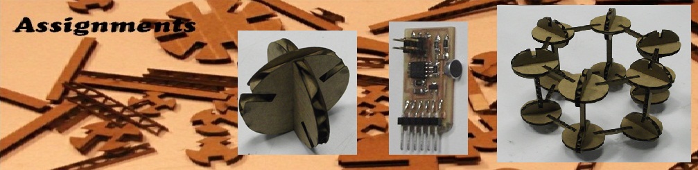

Assignments
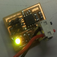
RGB LED Board
LCD Board
Final Project - Scanning Tunneling Microscope
I used this week to work on my final project. There where three issues which I considered this week explained below -
1) STM Tip Characterization
The quality of image you get from the STM depends upon the tip used. A typical STM tip should be sharp enough to have point width of the order of few micrometers. I characterized soldering wire, bulb filament and an probe station tip.
a) Soldering Wire - I attached the heavy mass to the soldering wire and then using hot gun melted the wire. The final tip width was dependent on the mass attached, distance of the hot gun etc.
b) Bulb Filament - Bulb filament is made of tungsten metal, ideal to be used as STM tip. In order to get the sharp tip I , cut the wire slightly inclined to the wire length , pushing upward.
c ) Probe station Tip - I used the commercially available probe station tip as a alternative for STM tip.
Characterizing STM tip -
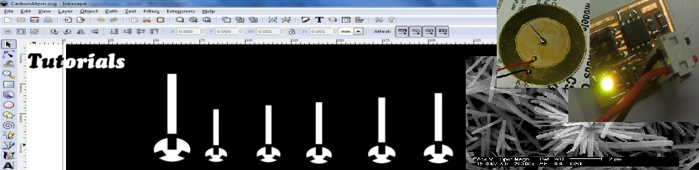
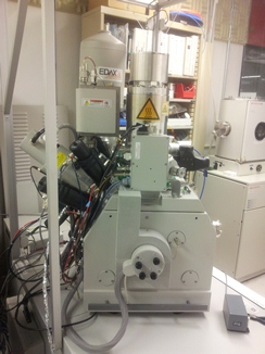
I mounted the tip inside the scanning electron microscope (STM) as shown below
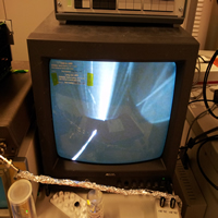
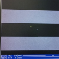
some SEM images for probe station top is shown below. It can be seen that the minimum tip width I got is of the order of ~ 20um.
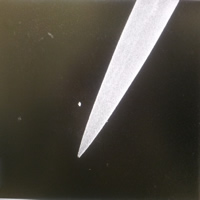
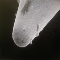
( Just to give an rough idea, Human eyes can resolve upto ~ 80um, human hair has a diameter of ~100um and It can be seen that end of the tip will be not visible from human eye)
2) STM Tip control
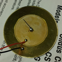
For imaging the tip should be precisely controlled in the range of few micrometer to nanometer depending upon the sample size and resolution. I used piezoelectric disk shown below as a possible solution to control the STM tip. The disk is divided into four parts using milling (modela).
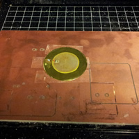
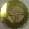
Now, controlling the bias in the four parts of piezo disk the lateral as well as vertical motion of the tip can be controlled.
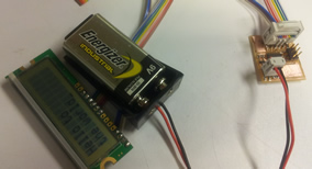
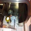
I designed the board to individually control the four parts of the disk. Sonicated entire system (battery, circuit board and tip assembly in DI water, Acetone, IPA) to clean organic impurity.
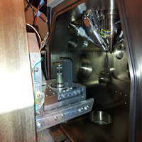
The entire assembly was transferred into the SEM chamber for imaging
Unfortunately, The bias was interfering with the electron beam and hence I was unable to image the motion of the tip with applied bias.
3) Sample Approach
The resolution with which the sample should approach the tip for initial arraignment should be of the order of few micrometer. Designing a system to get this much precision is a difficult job. For now, I used the laser motion assembly inside the DVD writer.
I hacked the DVD writer from an old computer
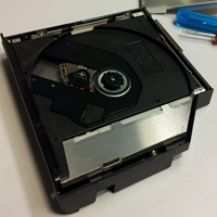
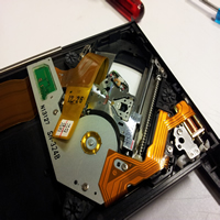
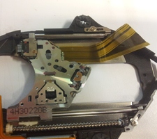
The assembly which move the laser head had a stepper motor. I designed the board to drive that motor. I was not trivial to drive the motor as I wanted precise motion.
Since, I hacked the system, I was not sure of the terminals of the stepper motor and what type of stepper motors is it.so I measured the resistance between each terminal to guess the exact sequence. Small tutorial is below -
Types of Stepper Motors
There are two types of stepper motors - Unipolar and Bipolar. In unipolar there can be a 5 wire or a 6 wire unipolars as shown below
a) 6 Wire Unipolar b) 5 Wire Unipolar c ) Bipolar
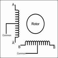
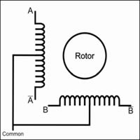
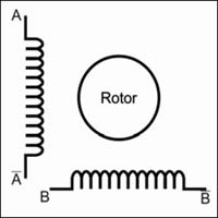
Identifying Common Terminal
By looking at the diagram of 5 wire unipolar motor we can see that the resistance between common and any other terminal A, A',B and B' will be same and the resistance between any of the terminal viz A, A'.B,B' will be twice as much. Similar resistance measurement approach can be used for 6 wire unipolar and bipolar stepper motor.
Finding the sequence
Give low to the common terminal and try giving high to the other wires in different sequence one by one. The sequence which gives you a clockwise rotation will give you the consecutive terminals.