Final Project:
Soil Moisture-Controlled Peristaltic Pump
First of all, I just need to declare: IT ACTUALLY WORKS!!! Sorry, but it's been a rocky journey, literally involving blood, sweat, and tears. ...and I almost burned down the lab. BUT IT WORKS.
To celebrate my excitement, here is a video of it working:
Another video, but without the soil:
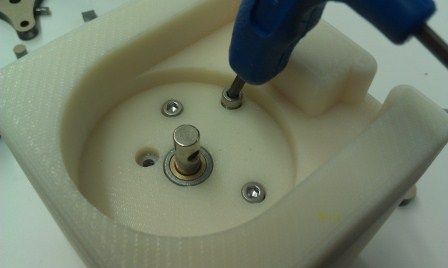
I decided to go with a peristaltic pump after an in-class design review. As you can see here, I had originally planned to make a baby centrifugal pump. However, Prof. Gershenfeld pointed out that a peristaltic pump is a lot less messy, because no seals are required--plus I only need a very small flow rate anyway.
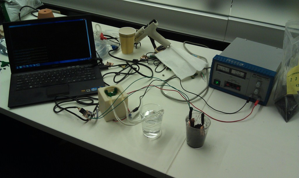
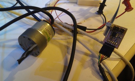
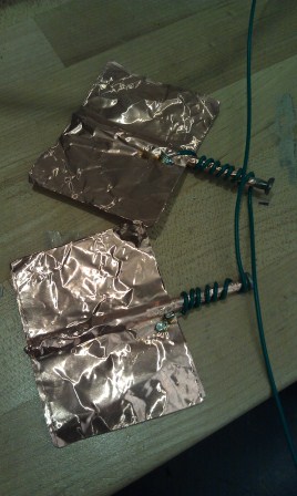
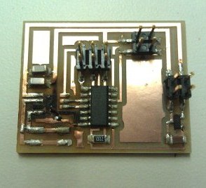
My system involves a pump driven by a gear motor, a soil moisture sensor (made with a step response transmit-receive board), and a Python program on my computer to talk to each of them. A bus connects the motor board to the soil moisture sensor board so that they can share an FTDI connection. Specifically, the bus connects the Tx and ground pin of the FTDI to the pump board. The sensor feeds data into my Python program through the serial port on my computer, and my program sends a character to the motor depending on the incoming data. The program sends a '1' when the capacitance is above a certain threshold to tell the motor to turn on and a '0' when the capacitance is below a certain threshold to tell the motor to turn off (because low capacitance indicates the presence of water in the soil).

Seems pretty simple, right? Yes, it is indeed simple. But that does not mean it was that easy to put together...
Problems and Lessons Learned
I don't have time or space to go through all the problems I encountered, so here are the highlights:
Serial port: Couldn't find it for a while. And when I did find it, I was apparently using the wrong notation. For all you Windows users out there, you can simply put 'COM3' (or whatever number) as your serial port--no need for the backslashes you might find on tutorial websites.
Bus connection: For some reason, I could not send a character to my motor board. With the help of Nadya, I used an oscilloscope to discover that ground was not really ground. Matt helped me identify that why: there was a problem with my code. I had used the initialization part of the example bus code, but I actually did not need that in this situation. After removing that line of code, my motor could receive characters from the computer.
H-bridge: After I got a character to send, my motor would still not run. I checked with a multimeter and discovered that two high voltages were coming out of the H-bridge (both out1 and out2 pins were 7.5 V) instead of one high and one low output. Turned out this was because my battery was dead, and I was able to run the motor with bench power supply.
Motor screws: The screw holes on top of the motor, one might think, are intended to secure the motor to a housing. One would be wrong. This is what I thought, and when I tried to run the motor, it simply would not run. I heard a weird shrieking sound, and the bench supply showed a spike in current. Apparently, those screws are meant for stopping the shaft. When I tried to run the motor, I blew out the H-bridge. I tried to remove the H-bridge with a heat gun, but I ended frying the board and had to mill and stuff a new board.
In the end, these and other problems were all resolved, with a lot of help from TAs Brian, Matt, and Nadya as well as the IDC lab manager Charles and my classmates.
Huge THANK YOU to everyone who has helped me throughout this semester!!
Files.
CAD
Pump housing (for 3-D printing)
Roller
component 1 (for laser cutting)
Roller component 2 (for laser cutting)
Electronics Hardware
Motor traces
Motor interior
Sensor traces
Sensor interior
Code
hello.txrx.45.c
hello.txrx.45.make
motor_receive.c
motor_receive.make
sensor_pump2.py