the fabISP
Although it took me awhile to mill the circuit board, after stuffing, my ISP worked on the first try. I went with the classic design for no particular reason. Maybe some part of me wanted to wrestle with the leads on the micro USB port, which was by far the hardest part to solder. Anyway, there are three main steps: milling, stuffing and programming.
milling
I followed the milling tutorial, using the Modela miling machine to etch away the non-traces on the board and cut it out. I ran into a few problems...
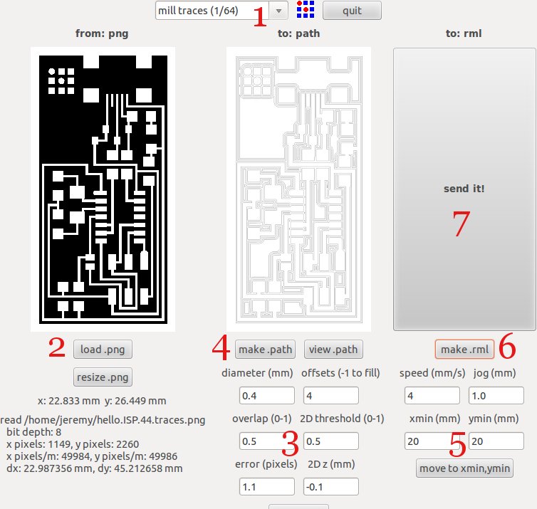
First, I adjusted the origin of the Modella AFTER I had created the RML file. The result was that when I hit SEND, the Modella would try to start milling somewhere else. In general if you are adjusting settings in fab_modules, don't hit the MAKE button until you're done with the settings in one process (e.g. making the path, making the RML).
Second, because of this mistake, my old job was haunting the Modella. To get rid of it, I followed the instructions in the tutorial (holding down the UP/DOWN buttons, seeing the green light flash, and killing processes on the computer). Important: an old job is on the machine if the green light continues to flash for awhile after you let go. If it just flashes for a second and then goes solid, then you should be good to go.
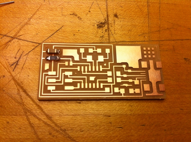
Third, I chose a terrible starting position for my first milling job. As you can see below, the Modella went off the edge of the copper board. It didn't damage the endmill or anything, but was a waste of time and material. Don't be afraid to choose the origin super close to the lower-left corner - this really is the bottom-left of the PNG, which is well clear of the circuit.
Lastly, you might notice that there's a lot of copper left on the board. This is because I forgot to pick the 1/64 setting in fab modules.
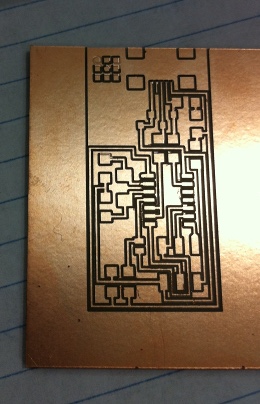
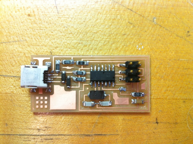
Finally, I ended up with a pretty nice board with almost no burrs. I closely compared the traces with an example-finished board to make sure there weren't any shorts or breaks. Forgot to take a picture right away, but here's the board after I had soldered a couple components onto it.
stuffing
Stuffing the board was fun, frustrating and took forever (3 hours). I mainly used an example board for guidance, but also referred to this marked up diagram. I followed Neil's instructions from class, and gave this helpful cheat sheet from a past student a once over.
My soldering process was as follows: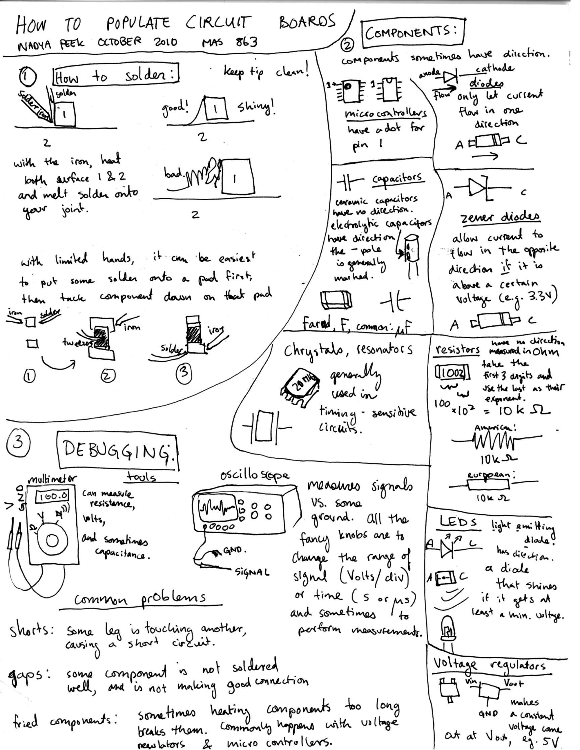
- Fix the board to the table using double-sided tape. Make sure the board isn't on the edge, so you can get your elbows on the table for more stability.
- Plan your attack. Neil says inside-out, bottom-top. The TAs say start with easy components, end with the tough ones. I did a mix. Do what you're comfortable with and make sure you won't have TOO much trouble getting at certain leads.
- Re-orient your board on a per-component basis, so that you're soldering the same way each time. I found that when I was sort of 'hugging' the board and had the iron/components coming in from the North, I wasn't as shaky.
- Make sure you have (a) the right component and (b) the correct orientation.
- Clean the tip of the iron on a damp sponge - should be shiny with solder.
- Tack down the component's first lead:
- Using just the solder + iron, drop a little blop of solder on the target trace/pad.
- Ready the component in tweezers in one hand, and with the other hand use the iron to heat the solder blob.
- Shove the component into place and adjust it until you're happy, then carefully remove the iron.
- Solder the component's other leads:
- Using the tip of the iron, heat both the lead and the trace. Wait at least 8 seconds!
- Bring the solder in and make contact with the lead or the trace, not the iron if you can help it. It should flow onto the joint, not the iron. For larger joints, use a bit more solder; for others, just a dab.
- Keep the iron there until you can see the solder has stopped flowing on the lead/trace. For large joints, wait around 10 seconds. For really small joints the solder doesn't move that much (e.g. the USB leads), so quickly bring your iron away in the direction of the trace.
- Go back and re-solder the first joint.
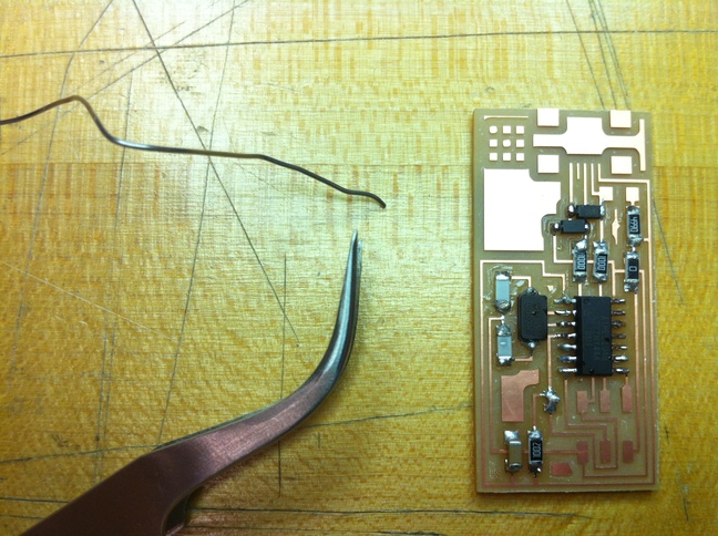
Here's my board in the middle of stuffing.
Some people said that since soldering quality goes up after your first joint, so you should 'work your way up' to the tough components: the microcontroller and USB port. While that was sort of true, I found that it took concentration and patience to get a good joint. When I took my time, got setup comfortably, waited for legs/traces to heat up and solder to flow, things worked well. It's hard to be patient for 3 hours though, hence the number of sloppy joints on my finished board.
programming
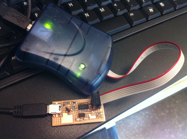
At this point you have to program your board so it can program other boards (<insert Xzibit meme>). I followed this tutorial to (1) power the board, (2) install software on my laptop, and (3) program the FabISP. I used the ATAVRISP2 to program the board, so I didn't have to change the Makefile.
The only trouble I had was knowing which way to plug in the ribbon cable. Here's my board plugged in - the red power (V) signal should be on the long-edge side of your board.
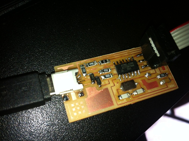
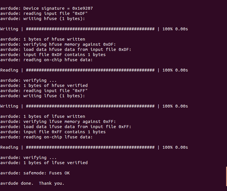
Luckily, everything worked okay and I got the green light and the following friendly terminal messages.
If this doesn't happen for you, I can only offer the same advice we got. Check your board for shorts and breaks in the traces/soldering, and make sure you have the right components/orientation. Otherwise, start over - your board will definitely be better the second time.
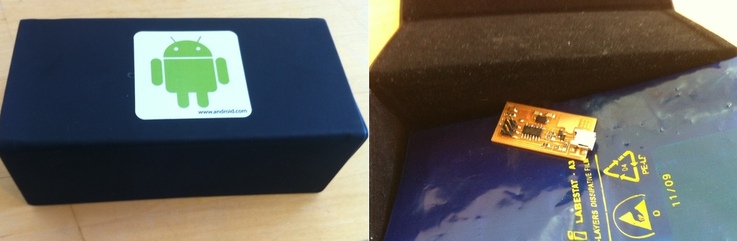
Lastly, I'd advise bringing a box so you can carry your precious ISP home safely.