Embedded Programming
Machine: Roland Modela
Material: Copper
Design Software: Arduino IDE
Share: BlinkButton_NMJ.ino

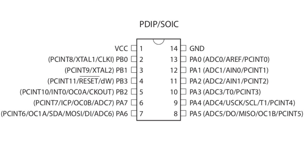
From the above schematics we know Arduino pins 0,1,2,3,4,5,6,7,8,9,10 correspond to our ATtiny44A's 13,12,11,10,9,8,7,6,5,3,2. This is essential for later on when we modify the Arduino IDE example code. Next we recap on some of the achievements from Week 5.

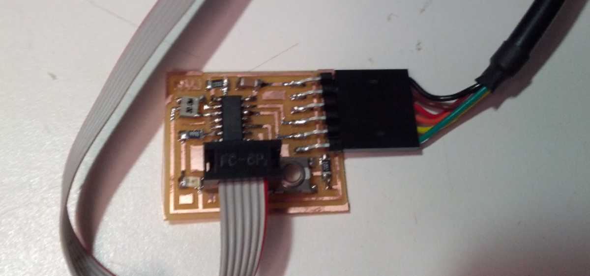
I programmed my board with the Arduino IDE. To provide avrdude with sudo permission I wrote 10-usbtinyisp.rules (with the line: SUBSYSTEM=="usb", SYSFS{idVendor}=="1781", SYSFS{idProduct}=="0c9f", GROUP="adm", MODE="0666") under /etc/udev/rules.d. With the IDE open I first selected "ATtiny44 (20 MHz external clocl)" from Tools>Board. Next, I selected "AVRISP mII" as my programmer from Tools>Programmer and ran Boot Loader to configure the fuse bits.
I tested my board using File>Examples>Basics>Blink with some edits to account for a different pin. I successfully uploaded this script, but my board did not blink. I realized my LED was oriented as cathod to anode, so I removed it with a heat gun and soldered it into the correct orientation. Now my board blinked, so I added some more code that turns blinking off while the button is pressed as shown in the video above.

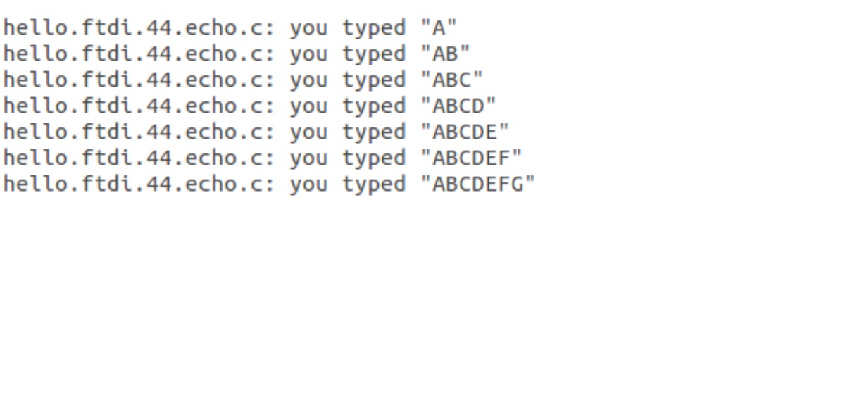
I then tested the ATtiny44A's memory with Neil's C code. The above output comes from the Arduino IDE Serial Monitor after programming the board with the command: sudo make -f hello.ftdi.44.echo.c.make program-usbtiny