Input Devices
Machine: Roland Modela
Material: Copper
Software: Eagle, Python
Share: hall-breakout.brd , hall-breakout.sch , hello.hall.FTDI.c , hello.hall.FTDI.c.make
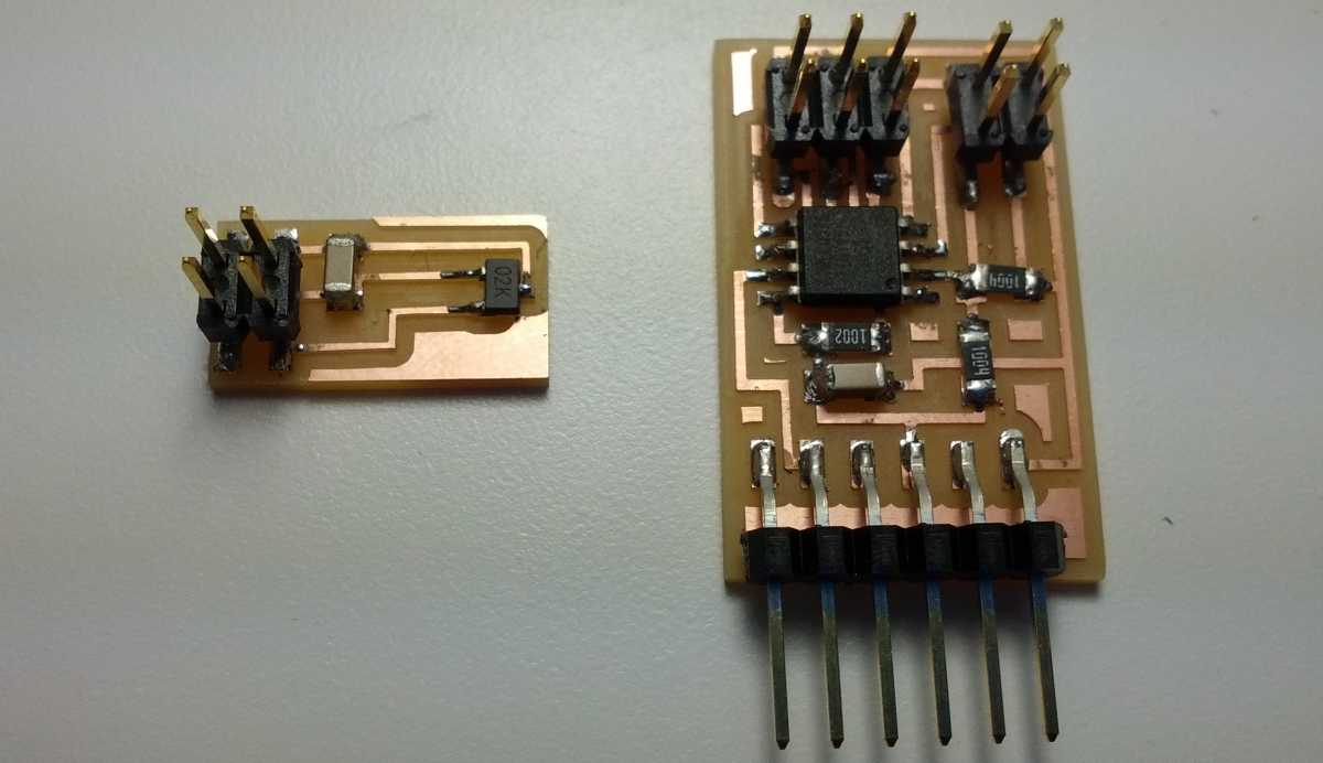
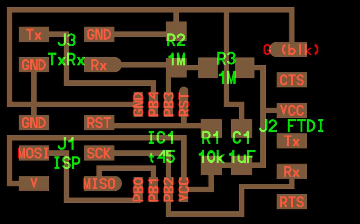
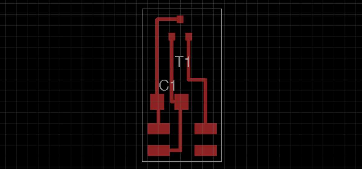
My input devices this week measure the hall effect and transmit-receive step response. The first (left below) is an extension for the LED + Button ATtiny44 board from Week5 following Anu Määttä's work during Fab Academy in Amsterdam and the second (right below) was designed and programmed with a ATtiny45 microcontroller following Neil's model.

I was surprised when I needed to insert the FTDI cable upside-down when programming my step response board. As expected, when running the corresponding python skipt in this orientation, there was no signal. Reversing the orientation, I was able to demonstrate three modes in the analog signal as shown in my video near the top.

I programmed the ATtiny44 to flash a binary output indicating the presence or absence of signal from the Hall Effect sensor. Pin 7 of the ATtiny44 had been previously traced to the header on the LED + Button board and was available to interface with the Hall Effect sensor attachment. The cable connecting this header to the 4 pin header was rearranged so the input/output voltage and ground were all correctly matched.
