Final Project Tracker
Week 1: Initial Brainstorming
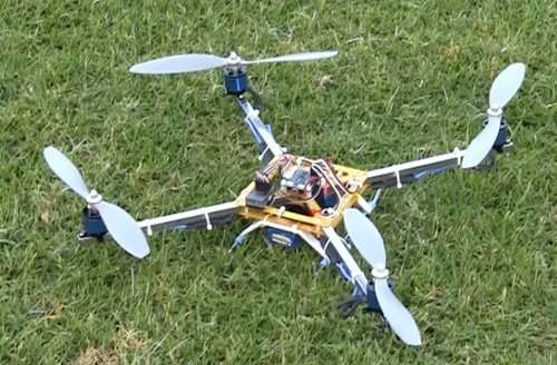
I want to try to incorporate the fabrication skills I learn in this class into my teaching, specifically through MIT App Inventor. I've taught many robotics-focused MIT App Inventor workshops for young students, and oftentimes, the students, families, or teachers want to get their own set of the hardware to continue the learning and exploration at home. However, many schools and families can't afford the LEGO Mindstorms we use (several hundred dollars each without all of the cool sensors and modular extensions). I want to see if I can make my own Wifi and/or BLE-connected robotic quadcopter set affordably, and if that works, I want to see if I can turn that into another lesson for the students.
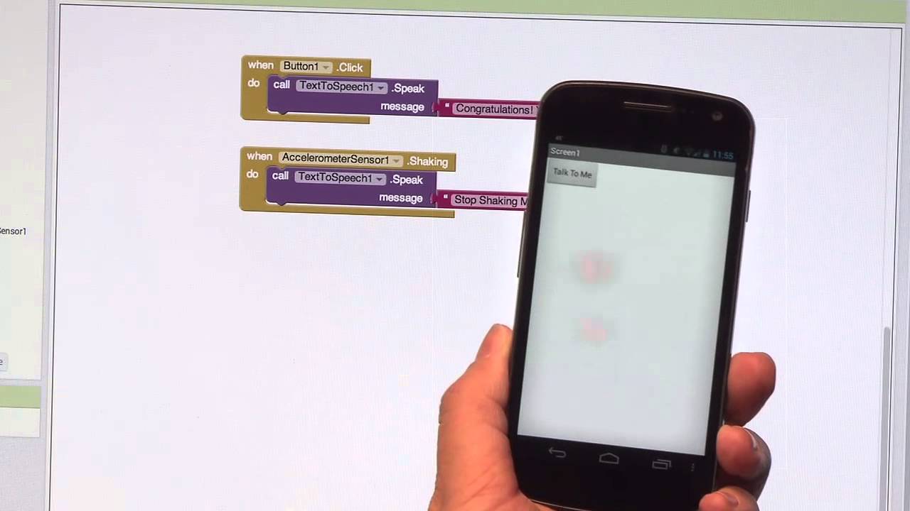
I've built a few of my own quadcopters from a purchased set before, so I'm relatively familiar with the pieces involved. I think much of the challenge will be in programming the quadcopter to communicate with a mobile phone running MIT App Inventor in real time. MIT App Inventor also has an extension for communicating over BLE. Although it is not too robust, I plan to build upon it to increase its functionality.
Week 4: CAD and 3D Printing Initial Arm Design
I did some research into quadcopter designs and found that many makers had shared their quadcopter building experiences online. I found these sites particularly helpful:
- Propellers, Motors, and Multirotors for Quadcopters
- Tips for 3D Printing a Drone
- Example 3D Printed Quadcopter
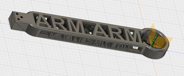
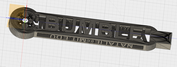
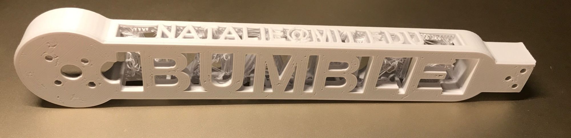
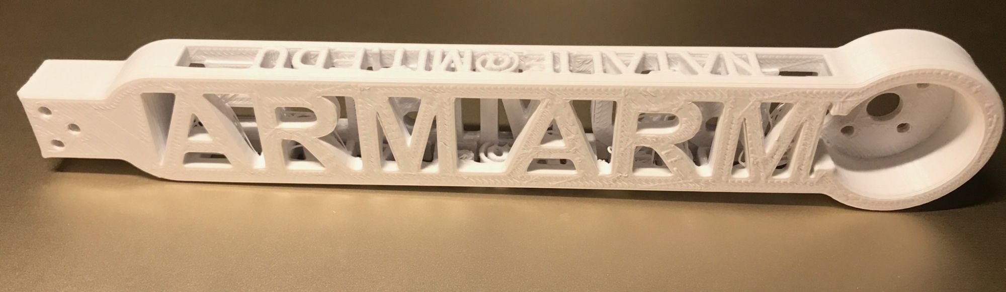
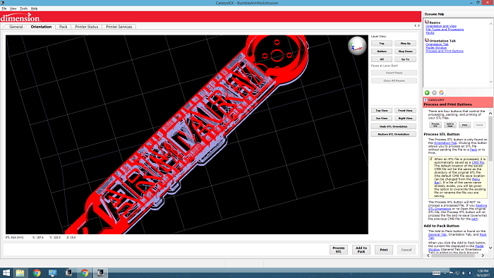
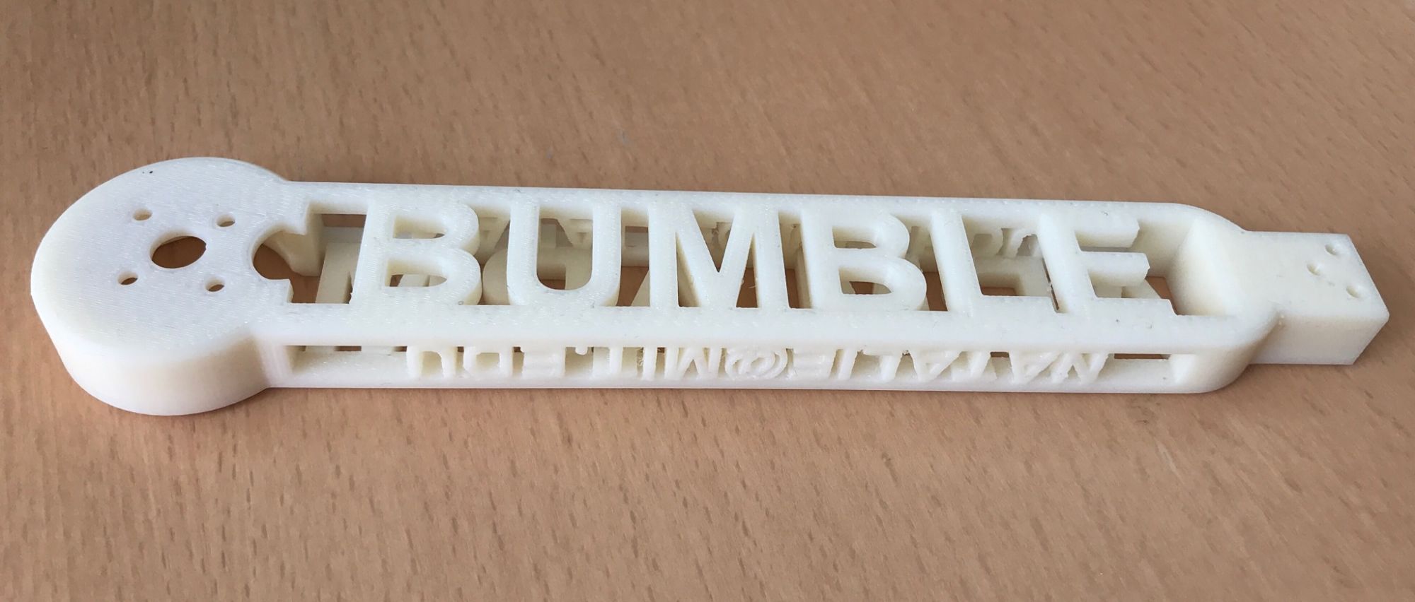
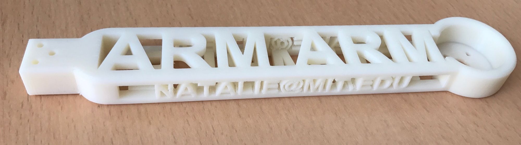
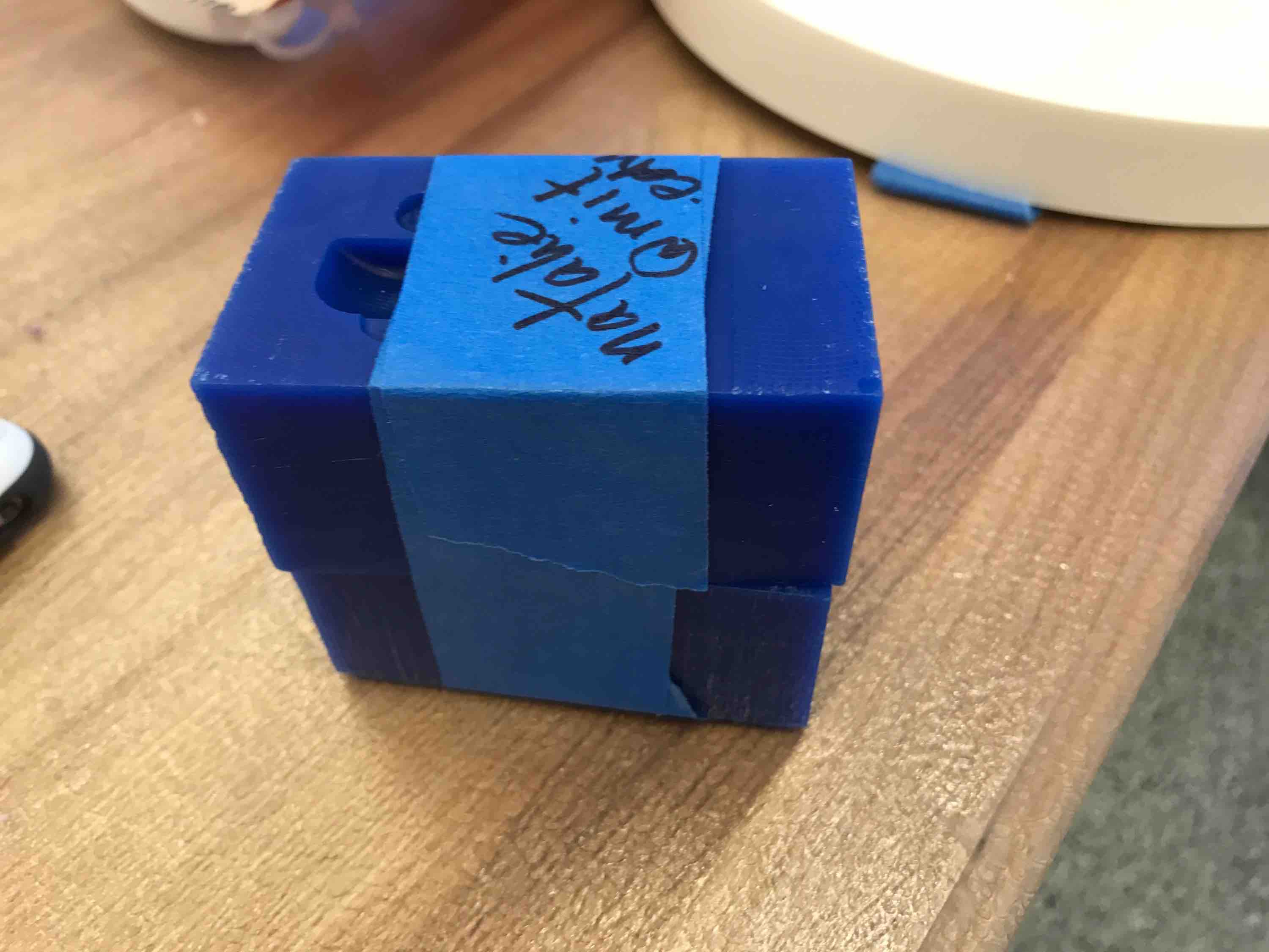
In order to fulfill the "additive" requirement, I made the main support structure of the arm a hollow rectangular prism with lettering along all four sides. The top reads "ARM" to identify the part, the sides read "NATALIE@MIT.EDU", and the bottom reads "BUMBLE", which is the name of my quadcopter. The circular pocket for the motor was designed to hold a 6cm motor. The entire arm was around 21cm. Some screenshots of my STL are below:
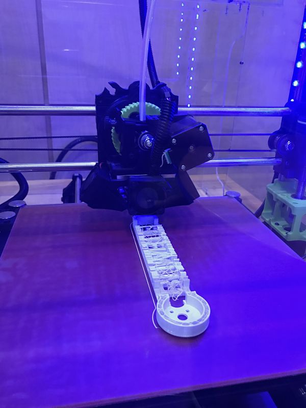
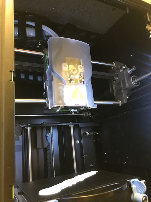
I initially tried to print my design on the Lulzbot without any support material, mostly due to the uprint machine always being unavailable. This started off pretty reasonably:
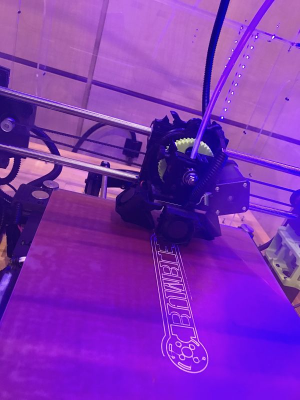
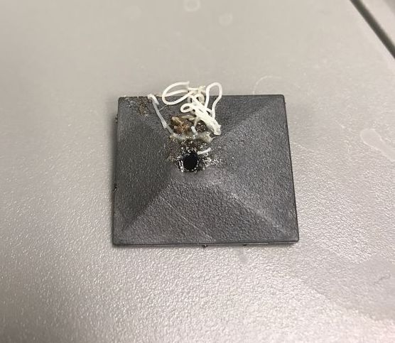
However, when the Lulzbot tried to print the top "ARM" layers of the object, the filament starte to sag and create imperfect birdnest-like strands in the middle space of the arm:
The final design was fine from the outside, but I was dissatisfied with the mess on the inside. Some of the letters of "NATALIE@MIT.EDU" also sagged.
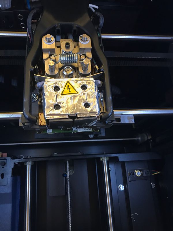
I went to lab several times to try to use the uprint 3D printer since it offers support material that can be washed away. However, the uprint was almost always already printing a job (as expected) and the timing did not match up for me to add my design to the pack. I finally got the 3D printer Tuesday night before class. Interestingly, the design started to bird nest after 2 layers. I noticed that there were a few clumps and strands of filament clinging to the bottom of the tool and asked for Dave's help. Dave showed me that the tip protectors seemed to be damaged and showed me how he changed them.
I plan to see how the print job turns out after class on Wednesday so that I can evaluate whether I should use 3D printing to create my quadcopter frame. As a preview to the final product, this is the toolpath for the filament and the support material on the uprint:
Update: I was very impressed by the result of the uprint. It took a little more than 5 hours to print and I soaked it in the support dissolving solution for 2 hours. Everything, including the inside hole portion, was almost completely clean. There were a few small pieces of support material that I had to pick off of the smaller letters on the side, but overall the design came out wonderfully. I did notice that this piece was noticeably heavier, duller, and smoother than the piece printed using PLA. This is probably because the ABS filament that the uprint uses is denser and has stronger material properties. I will need to do some stress calculations to determine the balance between structural integrity and weight for my quadcopter parts. A TA also suggested that I rotate the rod portion of my arm design so that the longer width is pointing down and the weights at either end can be better supported.
Week 9: Context Switch - Ornithopter with @akaspar
Since Neil has mentioned several times in class that something like a quadcopter is a complex system that is likely out of the scope of this class for one person, I started a search for partners on the class GitLab. Alex said that he would be happy to work together and we met to discuss the project. We decided to make the flying/moving part of the machine an ornithopter instead of a quadcopter (ornithopters are generally a bit more easy to make).
My part of the group project is to make a system that can "see" via a camera sensor. Using machine learning through a mobile application, it will be trained to recognize specific features (for example, my face) and then drop a candy if it sees that feature. This will work as a standalone system that can do sensing, image recognition training, mobile interfacing through Bluetooth Low Energy on an MIT App Inventor app, and control some sort of object/candy loader/dispenser. The idea is for this system to sit on top of the ornithopter. The ornithopter would be able to fly around and take lots of varied training images very quickly. It would also need to position itself to drop candy on top of a target (or the candy dispensing system would just need to be able to react quickly enough for the candy to land close to the target). I was planning for the item drop to be either a Pez dispenser-esque spring-loaded system, a simple claw, or a magnetic field system.
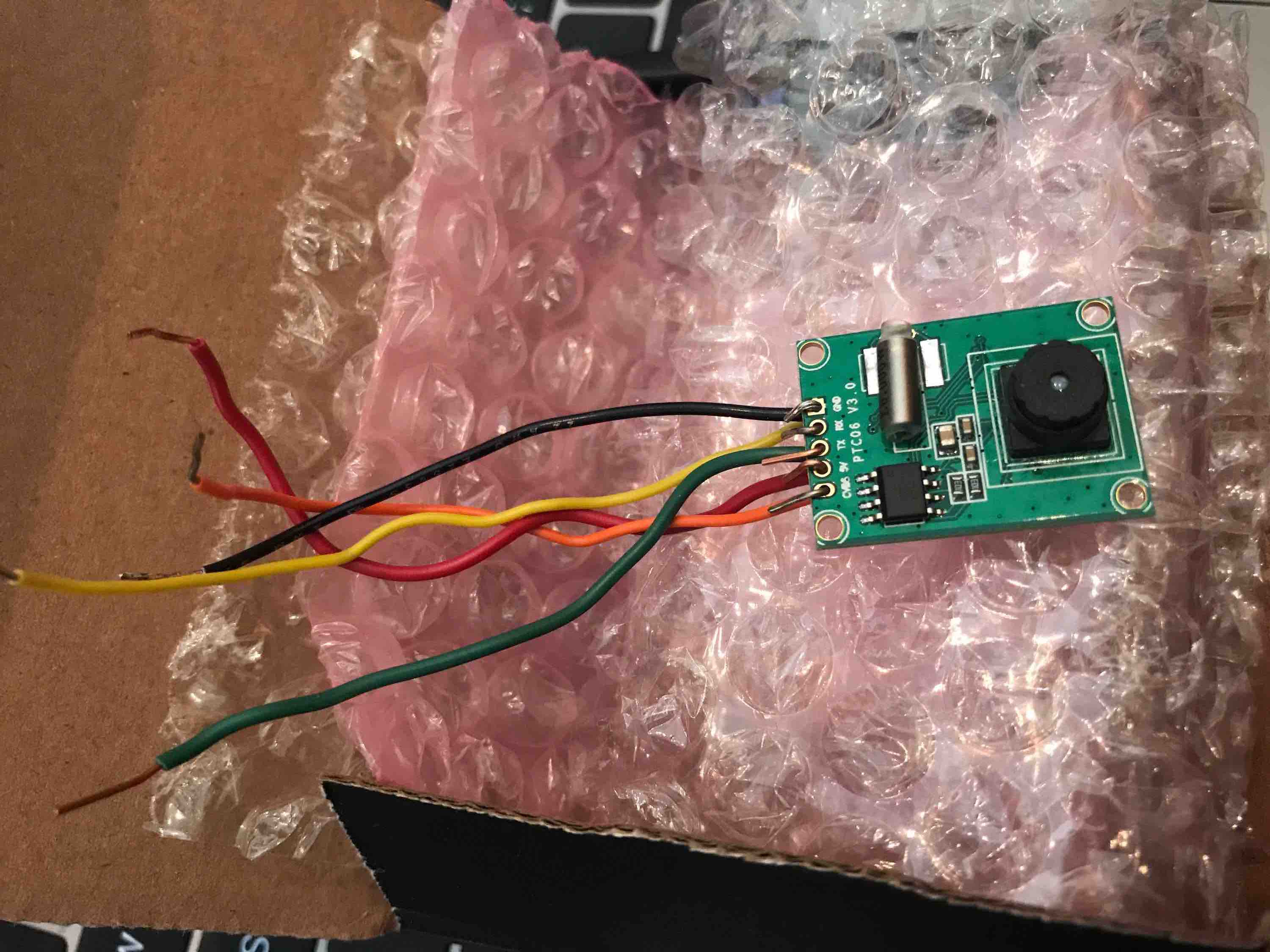
I decided to get the Adafruit Miniature TTL Serial JPEG Camera with NTSC Video due to its ability to both take JPEG snapshots and stream NTSC video.
Final Project
After a lot of research and trial-and-error in previous weeks, I realized that streaming video or even picture data requires an extremely powerful microcontroller and Bluetooth chip. Only the NRF52/BC832 chip in lab had the appropriate specs, but none of the students across sections ended up able to program it to send/receive over Bluetooth. I switched gears and decided to pursue an easier sensor: visible light/phototransistor. I also decided to use the RN4871 with the ATtiny44a instead.
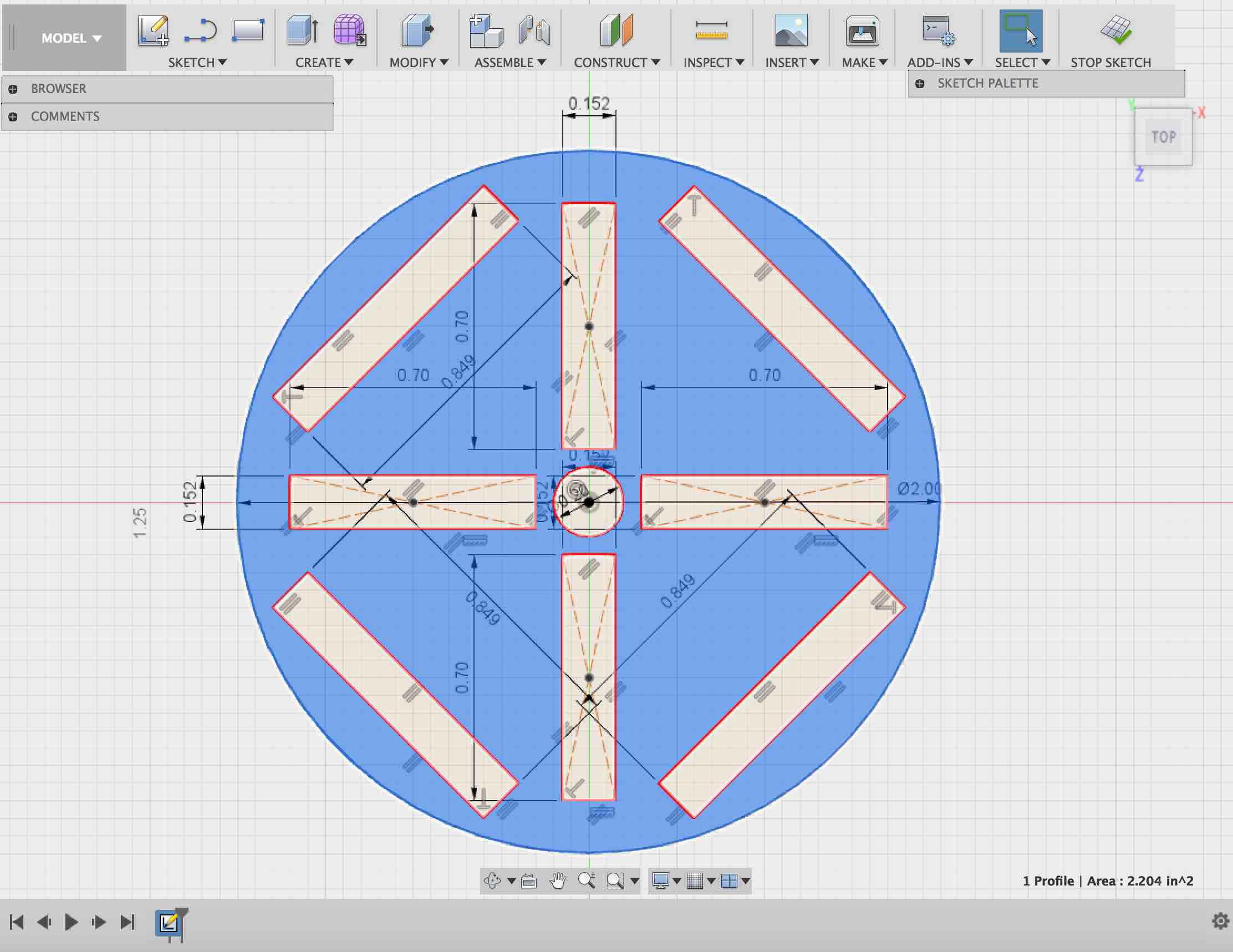
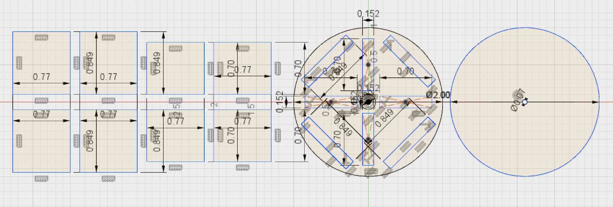
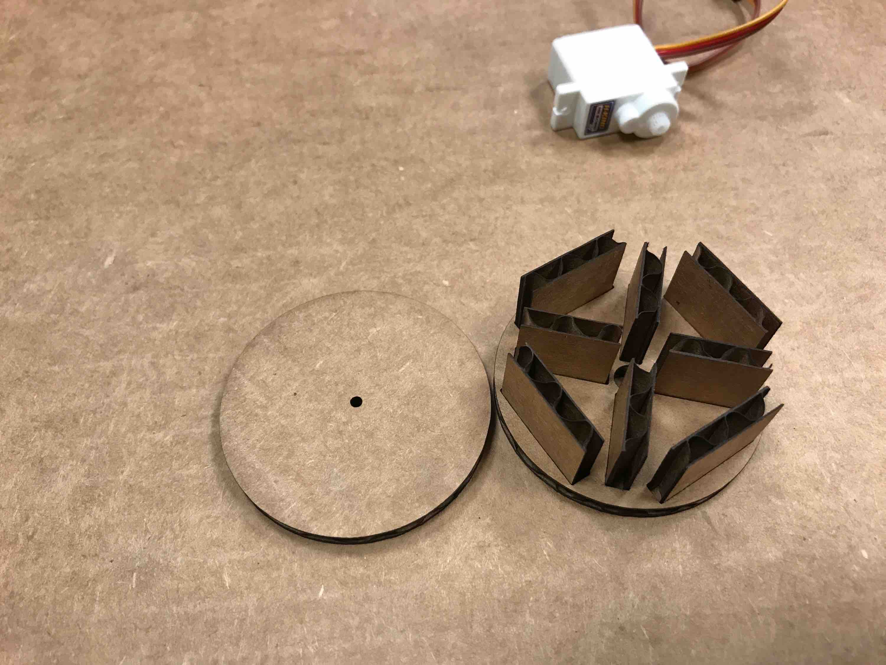
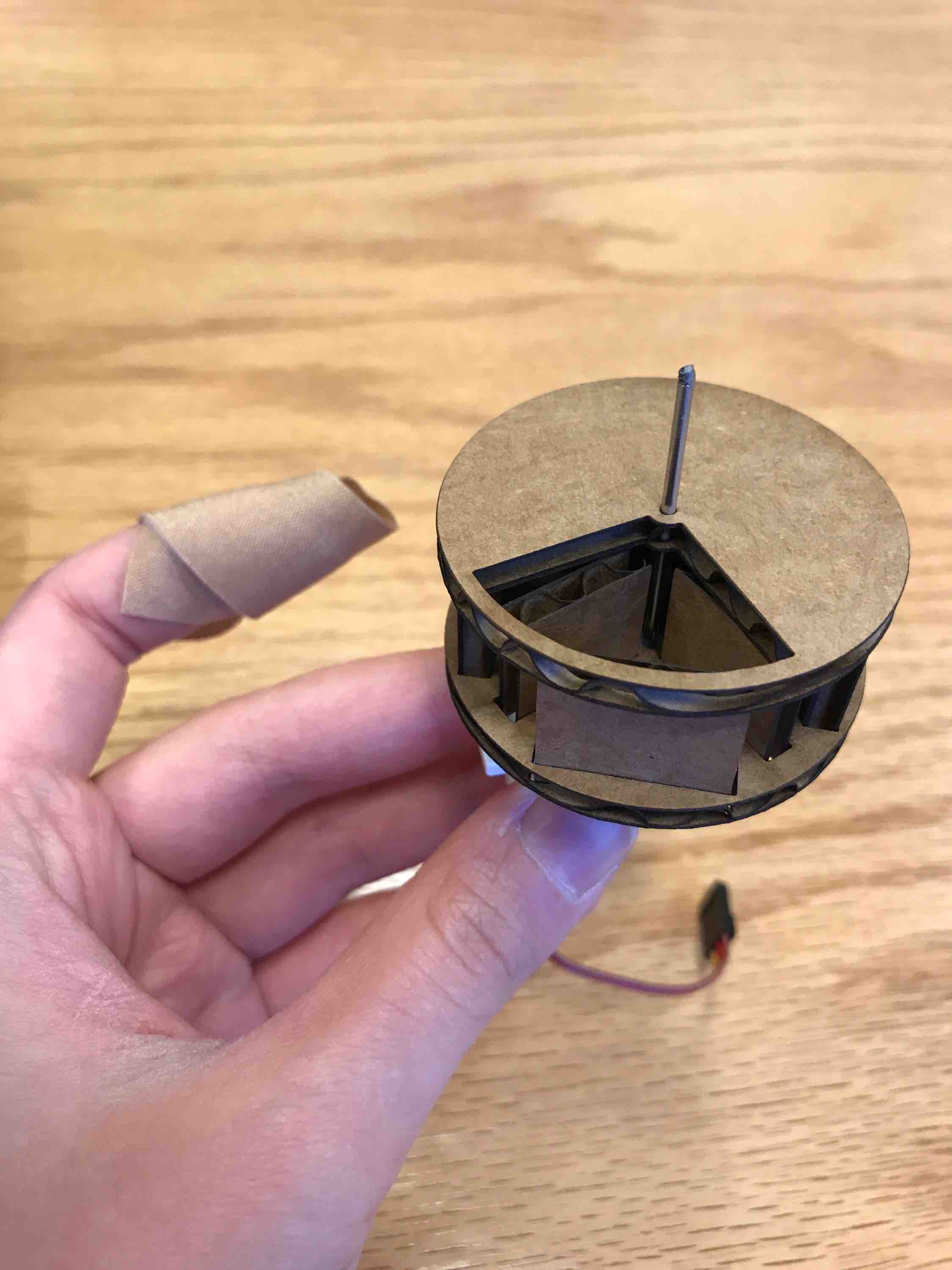
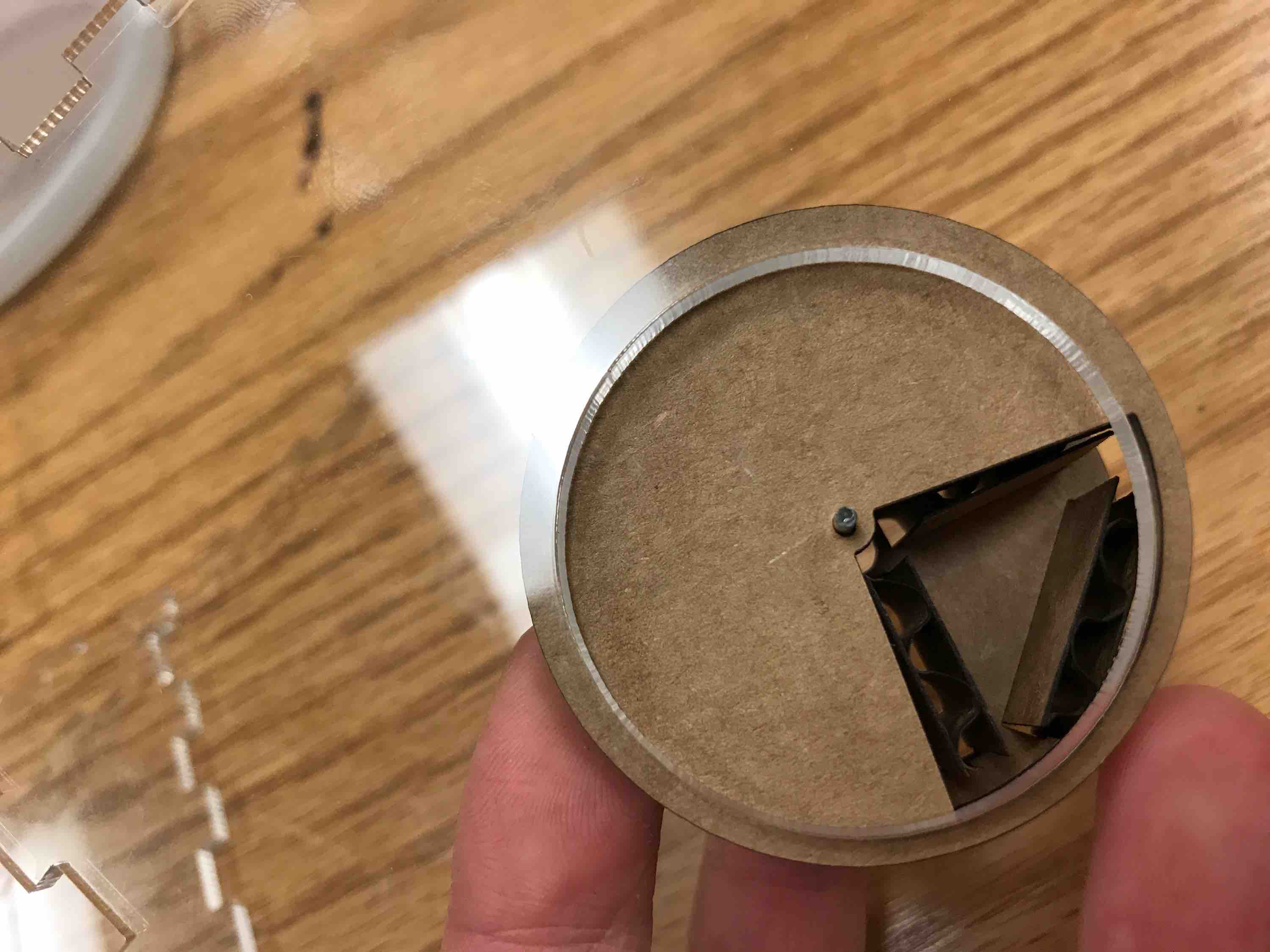
First, I designed the dispenser to have a compartment/rotational structure so that pellets would fall out when the slider moved over a full pocket. I decided to press-fit cardboard so that everything would be light on the ornithopter:
- base rotation circles 2 inches diameter
- Cardboard .152 in thick
- Four rectangular slots .152 in by .7 in
- Outer barriers are .141 in by .849 in
- Inner circle for servo shaft to go through: (1) Servo hole is 0.07 in diameter; (2) Inner hole needs to clear servo hole and fit snugly around the servo base (0.1875 in), so 0.2 in should be enough.
The upper circle just needs a center hole of 0.07 diameter for the rod connecting it to the servo. The balls being dispensed can be 0.4 in in diameter to fit into the triangular compartments: cast Oomoo? Hard to break after falling from heights and will be less likely to hurt anyone, but it may have friction issues with the rotating cardboard. 3D print?
Support structures for the press fit:
- Press-fit height 0.17 in > .152 in
- Since balls will be 0.4 in diameter, should have a 0.4 in+ height from there so 0.6 in height
- No lip to cut down on material weight
- Middle supports: 0.7 in by (.17+.6) = 0.77 in
- Side supports: 0.849 in by 0.77 in
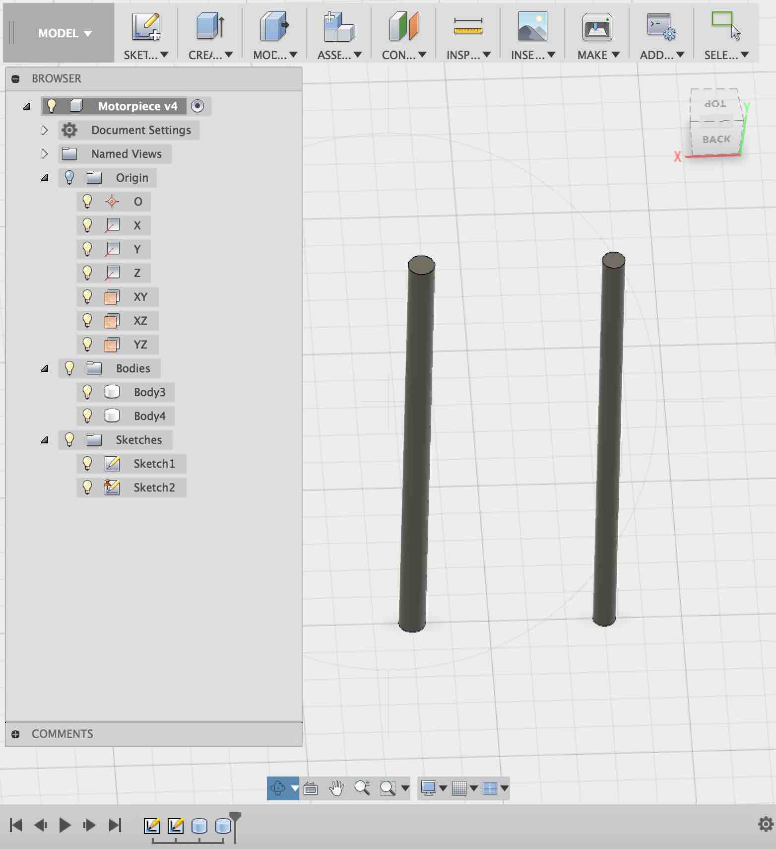
I need a small rod to hold the rotating piece to the motor: 0.07 inches in diameter from 3D printer should be fine since it is more than 3x the minimum feature size. This method may result in fragile pieces, but this is lighter than aluminum and we can easily replace it.
I will 3D print two .07 in diameter rods and two .06 in diameter rods in case there are kerf issues. Height of 1.3 in should be sufficient since supports are 0.77 in and it needs to go through the hole in the servo and the hold onto the top piece (0.77 + .152 + .2 = 1.122 in)
0.141 in as a hole size wored better than .152 in, so I redid the center holes on the base circle (.141 in x .7 in).
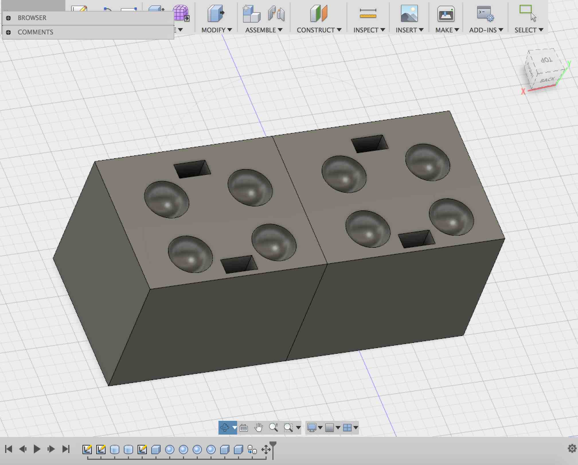
Specialized payload for dispenser
Since I want balls of a very specific size to fit inside the dispenser, I will cast them. The balls need to be:
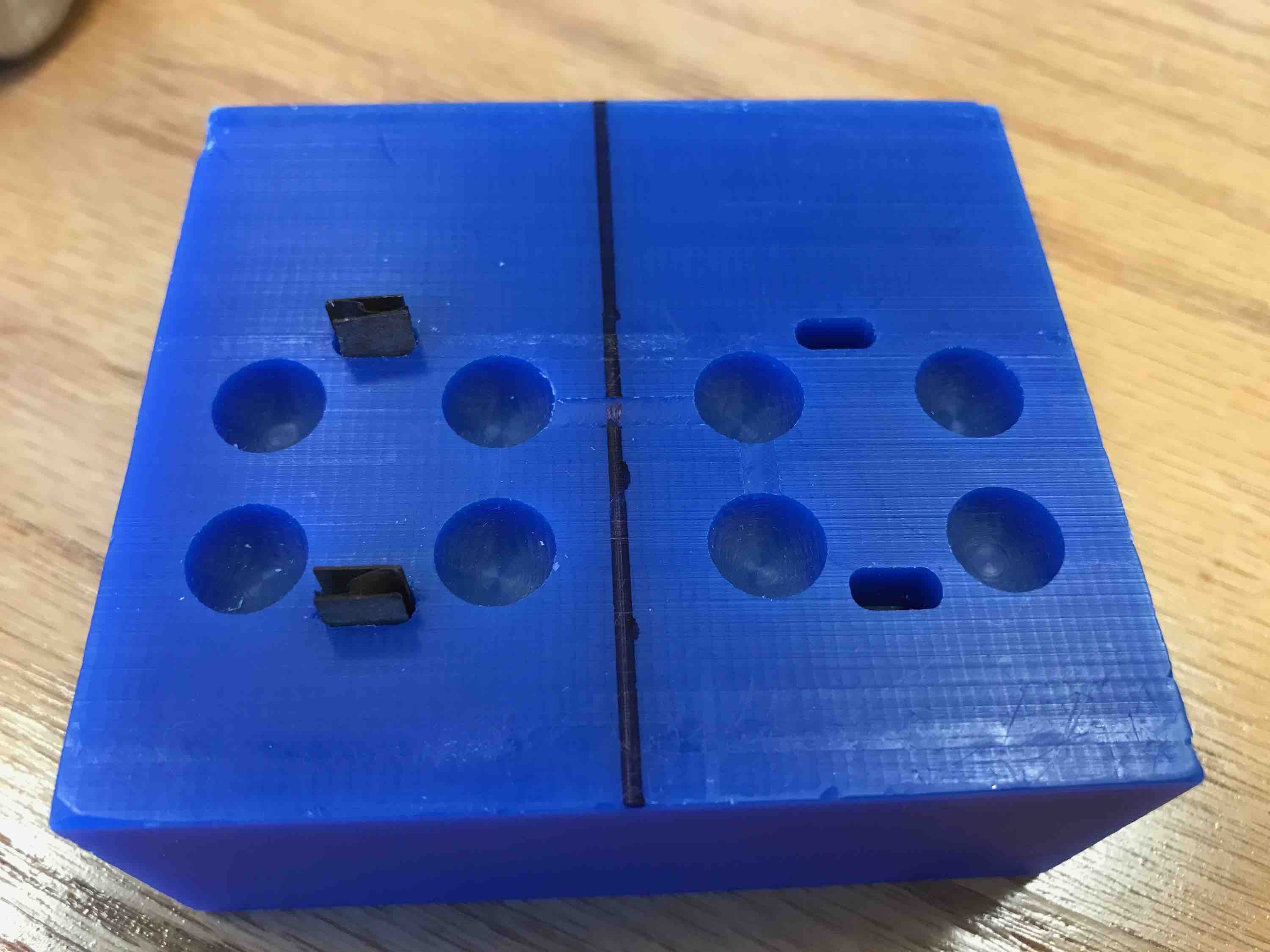
- 0.4 in diameter. I have a block of wax that is 1.4 in x 3.4 in. I will bandsaw the wax block in half to do the top and bottom molds so 1.4 x 1.7 in blocks each (height of 1.4 in).
- To fix the two pieces together during molding, I will drill mill square notches into the blocks and put form-fitting laser-cut cardboard pieces in these holes. The holes are .15 in x .3 in x -.3 in.
- Note: in fabmodules, 0 has to be the corner close to you and on the left.
The cardboard pieces have width ~.15 so I need to make .3 in x .55 in cardboard support pieces so they don’t make the two-part mold jut out away from each other when they are pressed together. In order to be able to snap together the two pieces quickly, I only have two fixing holes instead of more (friction). I also cut a .28 in x .5 in set in case the larger set is too frictiony.
In the meantime, I also re-cadded the top circle to have a smaller hole (0.05 in) to fit the motor rod snugly. I also added the hole for the ball to fall through. The 3D printed rods disappeared/melted so I decided to use aluminum rods instead.
The smaller mold support pieces fit really well:
After cutting the two-piece mold apart with a bandsaw, I tested out the support but realized that the cardboard was too thin/bendy to serve as good supports. I will try to make them using acrylic. Measuring the post-processed wax holes gives me 0.296 in x 0.149 in. Using 1/8in acrylic should be enough. I will try cutting 0.55 in x .29 in; .55 in x .28… to 0.26
- 0.26 was too loose
- 0.27 was about right
- 0.28 was very snug but I think it will work best because there is no sideways motion when the two blocks become attached.
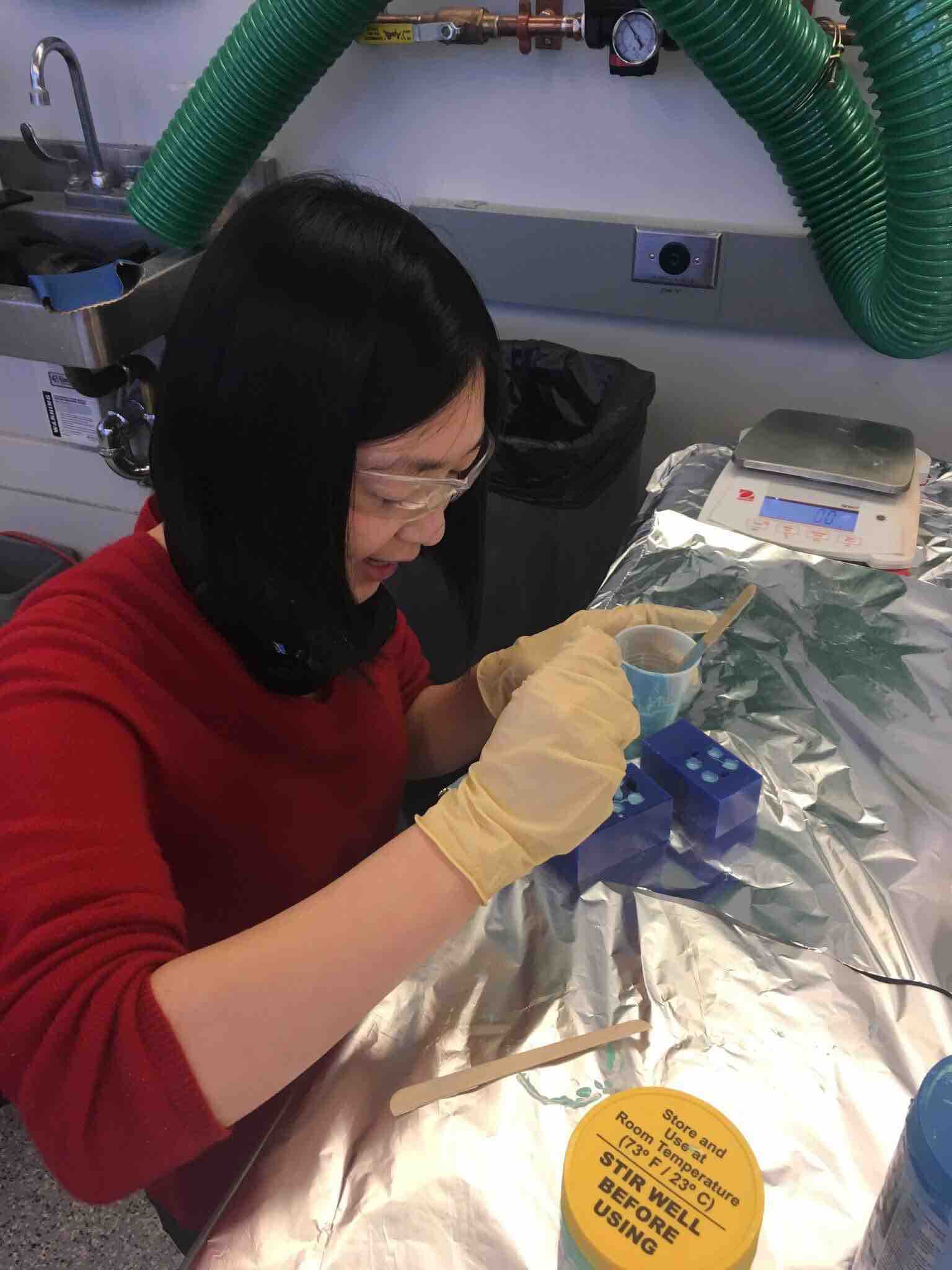
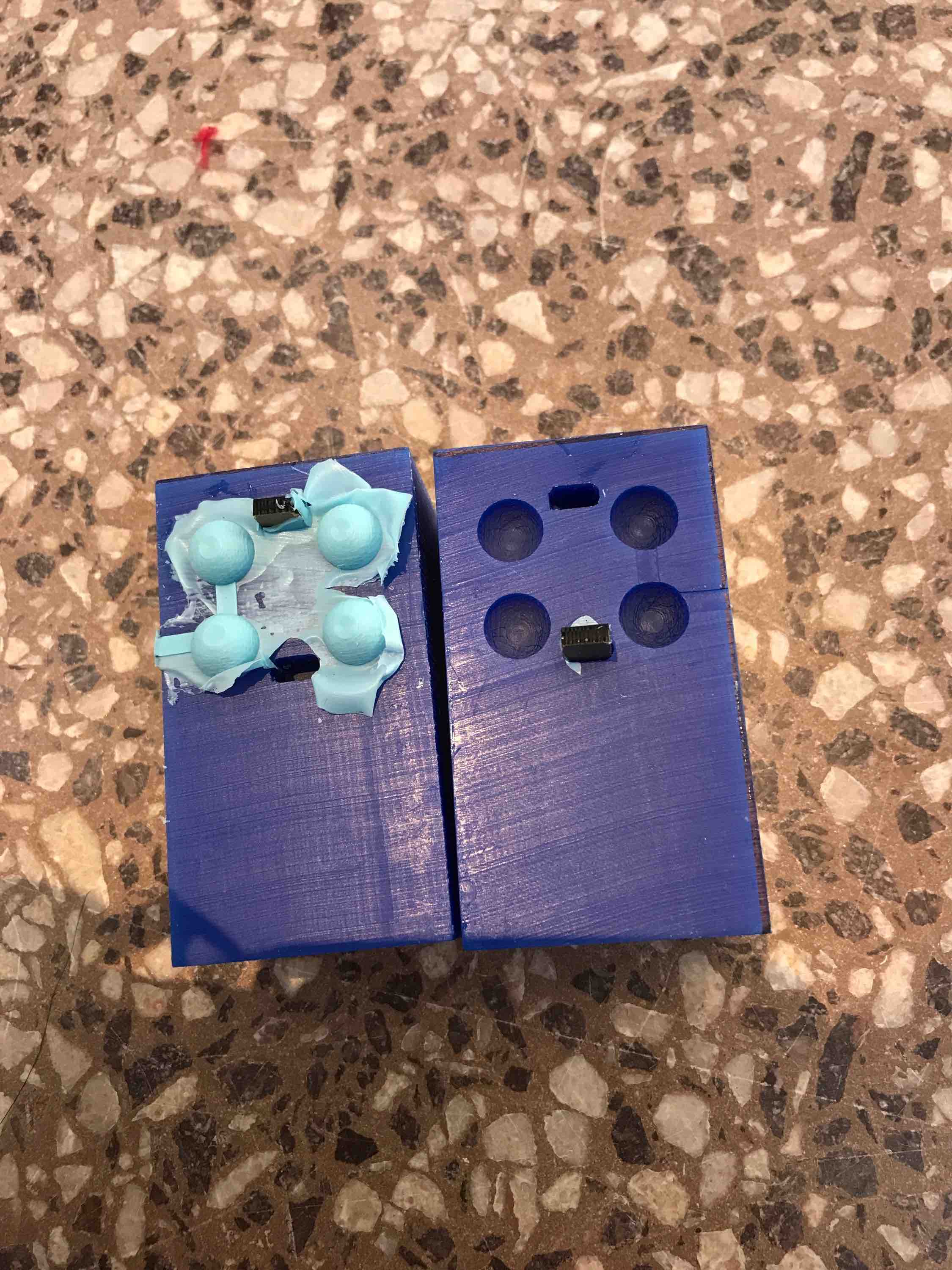
I mixed a small quantity of Oomoo for the little soft balls. I broke a popsicle stick in half to paint the Oomoo on the sides of each hole to make sure the outside will be evenly coated. I then carefully dolloped enough Oomoo into the holes: filling up the one with the acrylic piece a bit more than halfway and the other one around halfway.
It was a bit hard to avoid getting the threads of Oomoo on the wax, but I wiped it as well as I could.
I let the Oomoo set for a few minutes more before attempting to push the two blocks together. It was still a bit flowy, but not everything fell out when I attempted the mushing (which took a second longer than ideal due to having to push the acrylic pieces in to the slots). I bound the pieces together with tape, which had an additional clamping feature. I then rotated the orientation of the blocks every 2 minutes until all sides were covered.
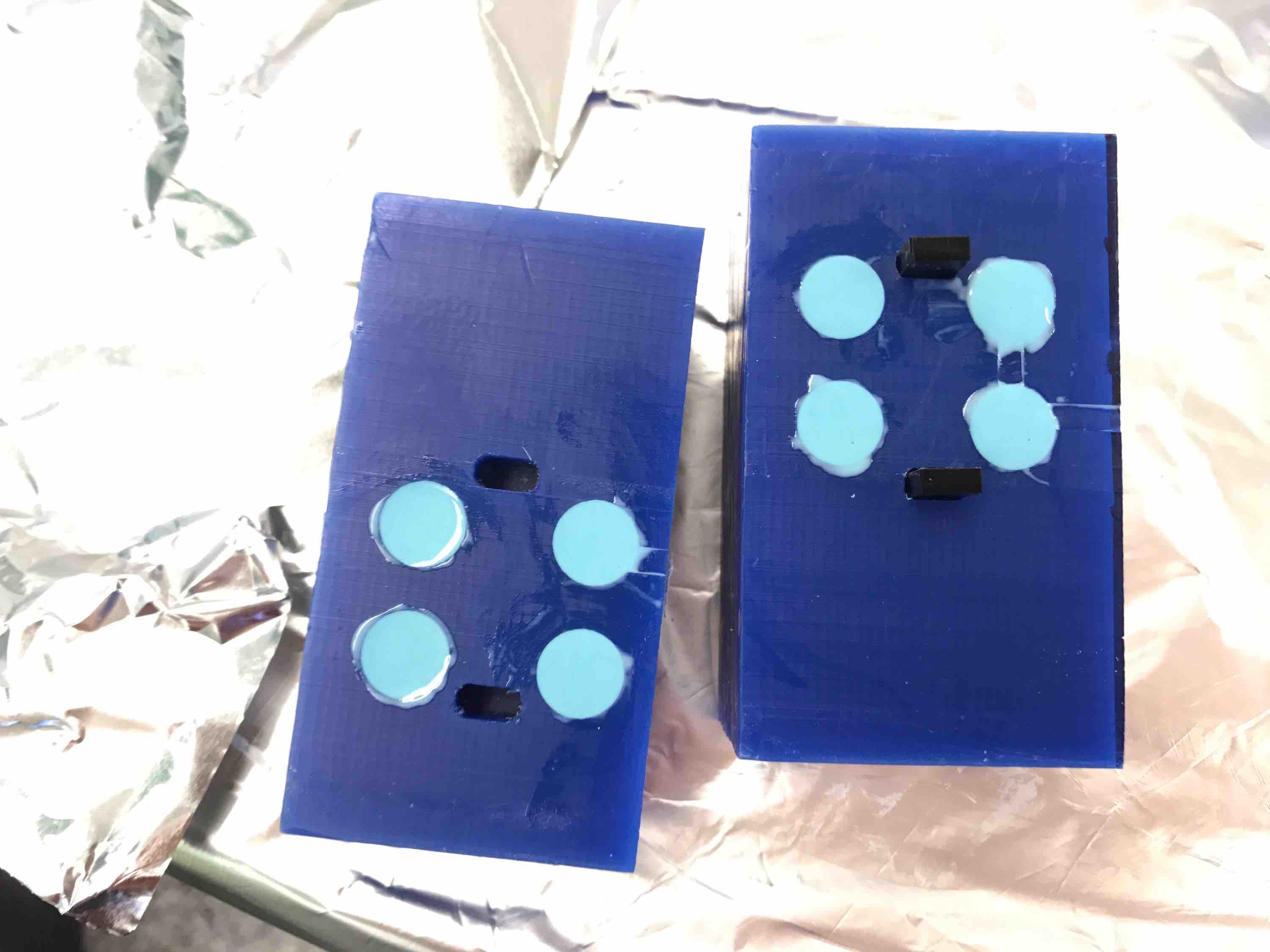
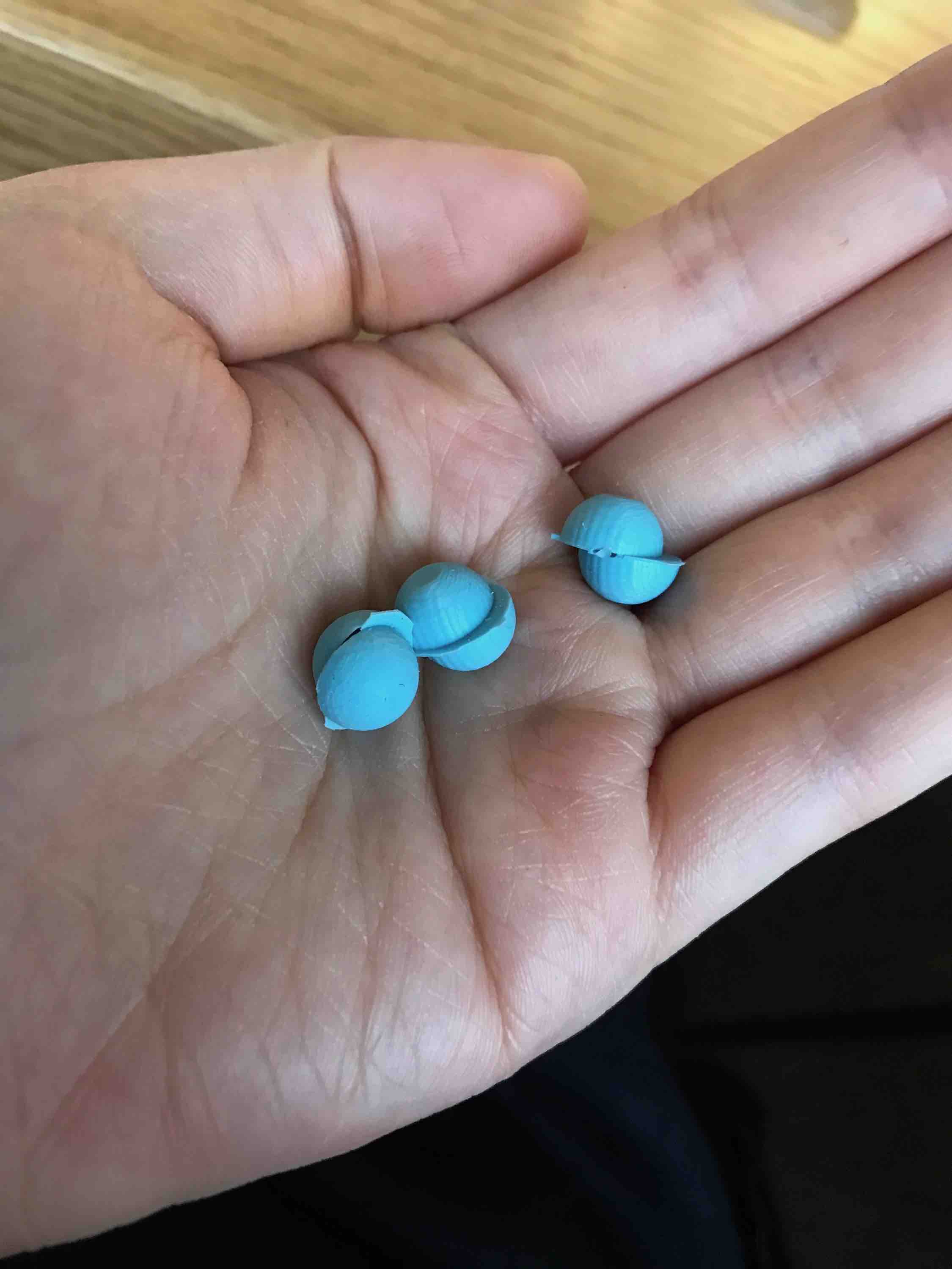
The balls ended up being badly offset. I discovered that one of the mounting support holes in the CAD file was slightly off center.
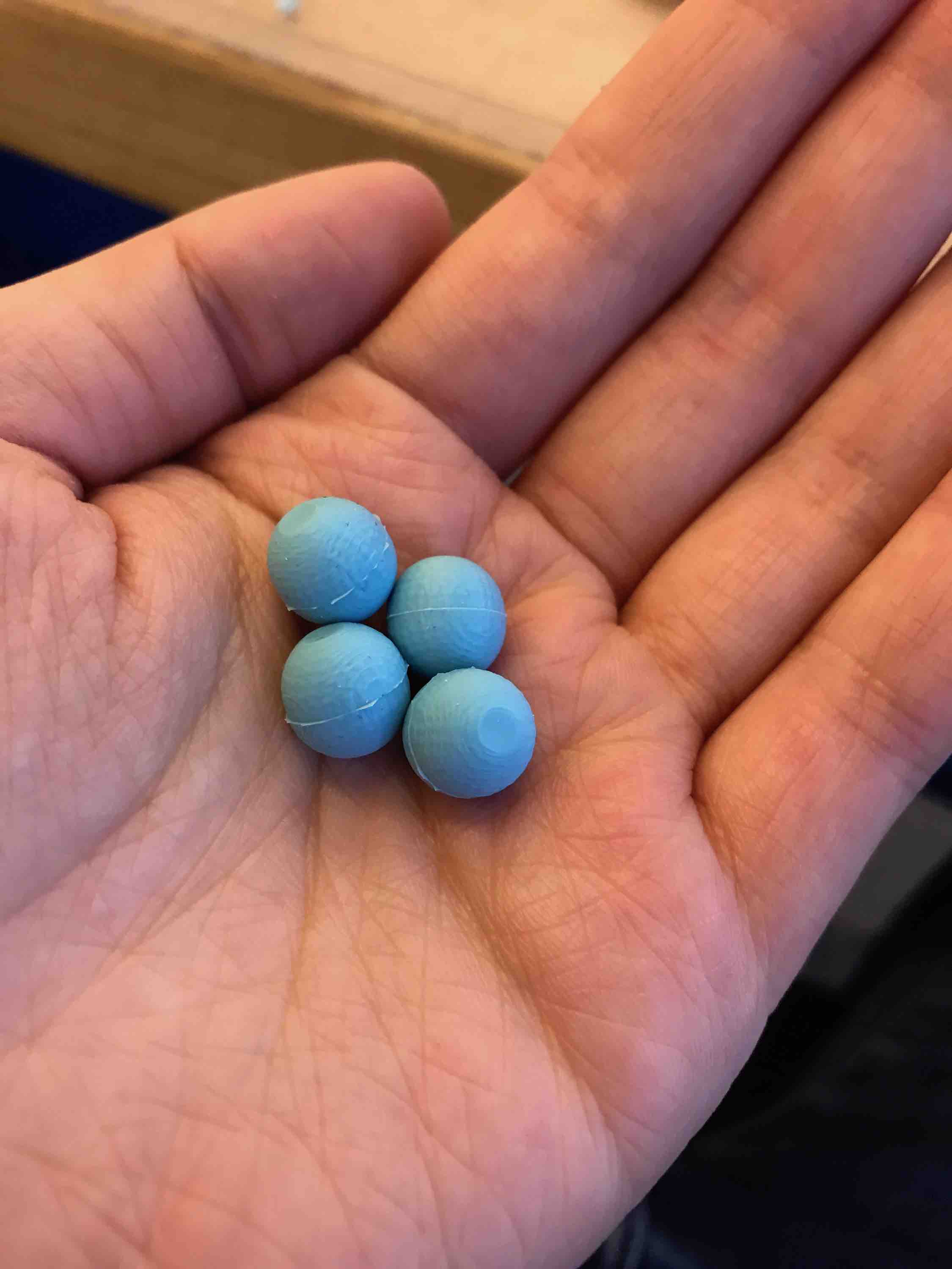
I added lines to my Fusion 360 file to make sure the new hole was centered. The second round of casting was much more successful:
Final Board
I was unable to get the NRF52/BC832 chip to send messages over BLE two weeks ago, so I switched focus and decided to try using the RN4871 BLE module instead. I made a combination of the dual-servo board and the RN4871 board, with the following key changes:
- I connected a visible light sensor (phototransistor) to ATtiny44A’s PA0/13 (8-bit I/O).
- I connected RN’s P2_7/15 (GPIO) to ATtiny44A’s PA2/11 (8-bit I/O).
Since the BLE operates at 3.3V and the ATtiny44a must operate at 5V to run the servo motors, there is a need to do 3.3V/5V level shifting for when the Bluetooth chip has to transmit to the ATtiny and tell it to spin the motor. There is a translator chip called TXS0104: http://www.ti.com/lit/ds/symlink/txs0104e.pdf. For that chip, the OE is output enabled (if I want it constantly on, connect to VCC). I also need to add small bypass capacitors and make sure I connect the larger/smaller voltages to the correct port.
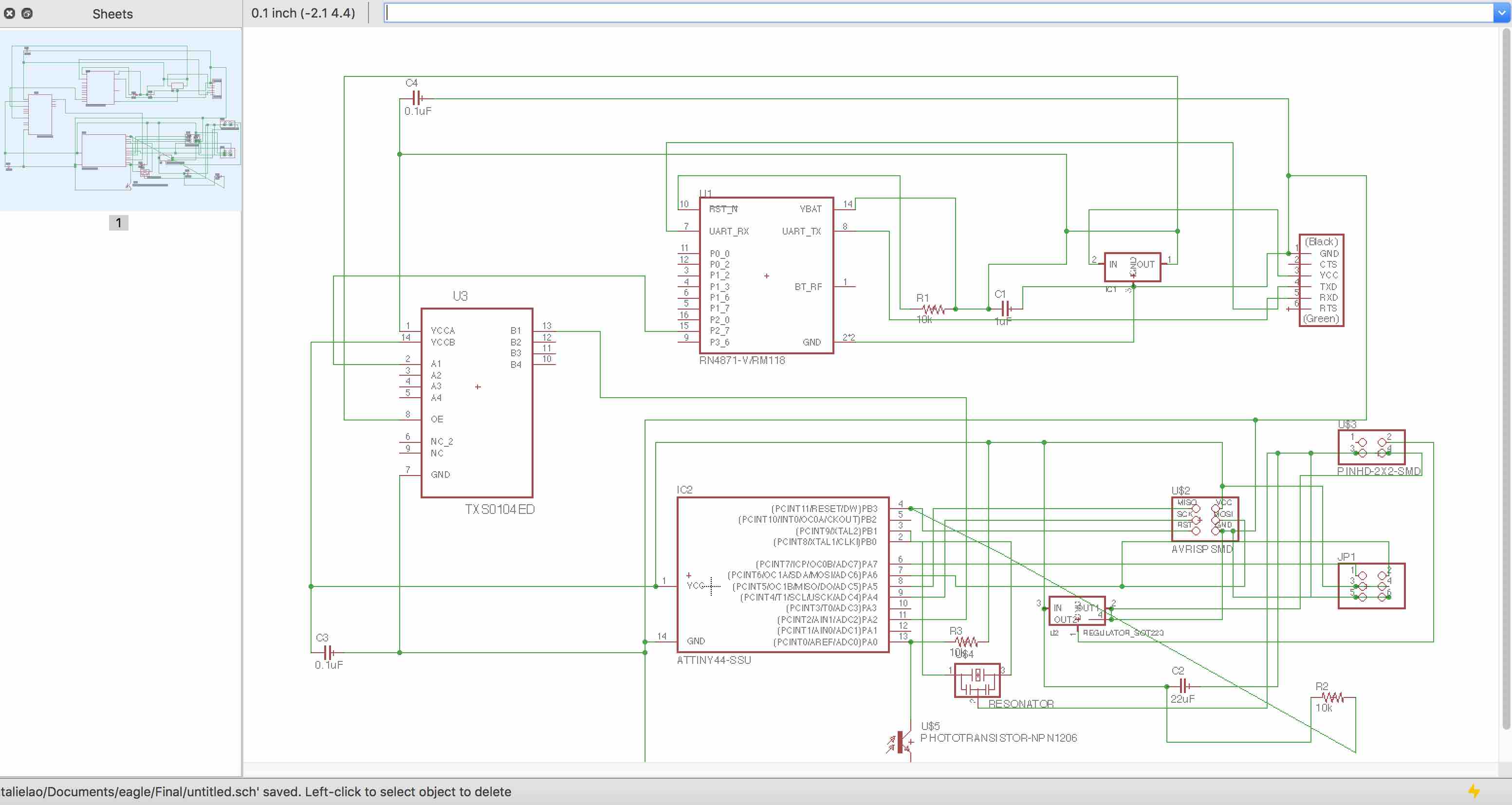
Here is the final Eagle schematic with the Bluetooth module, visible light sensor, ATtiny for the motor and the voltage translator in between.
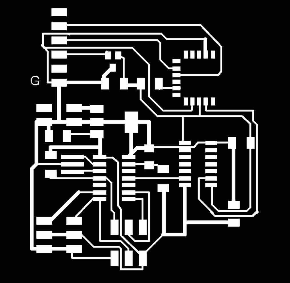
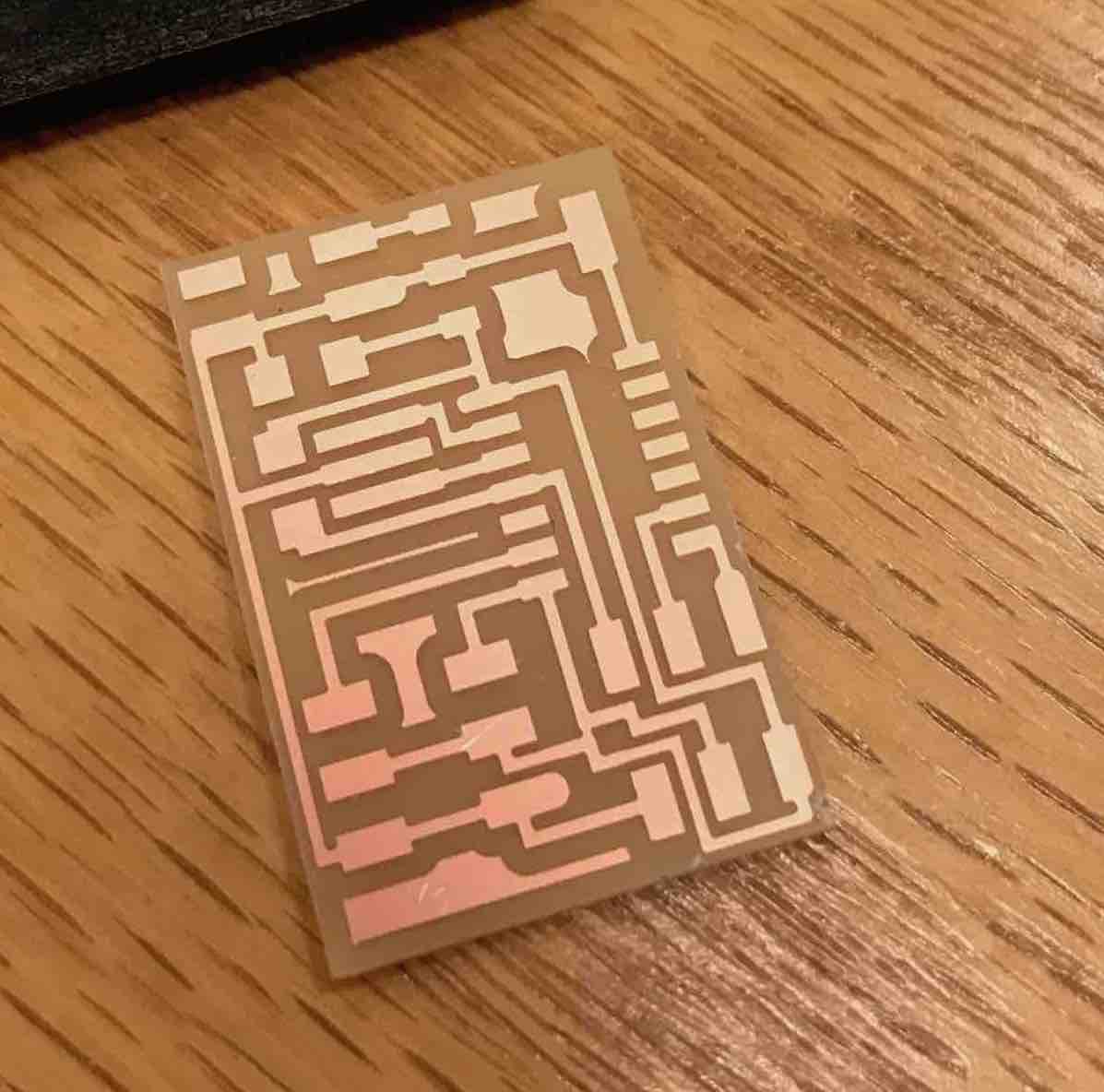
The board design looks like this:
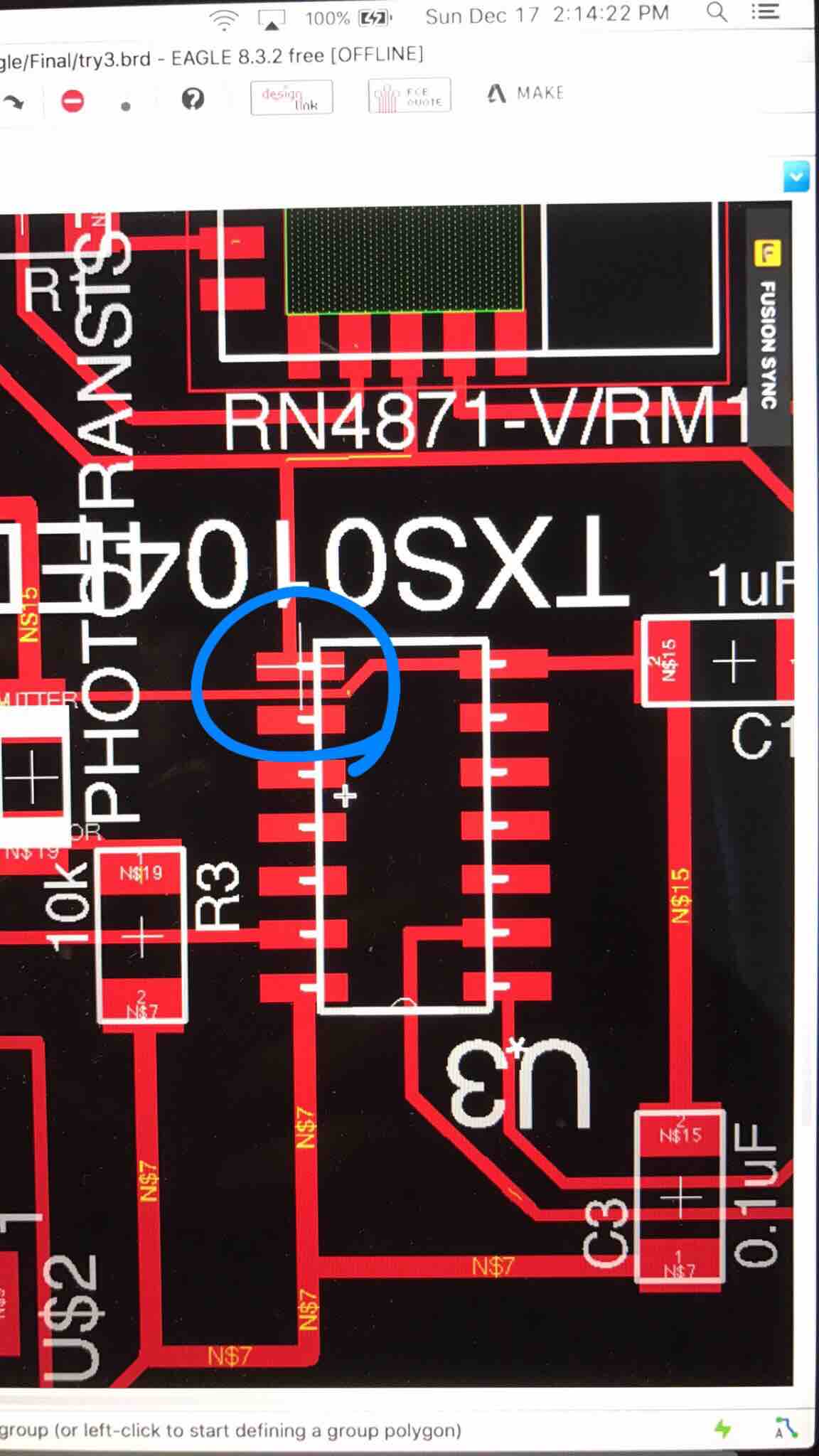
I had trouble making the routing on the ATtiny work so I have the idea of cutting or bending off the necessary ATtiny pins that I’m not using in order to accommodate the route going underneath the board.
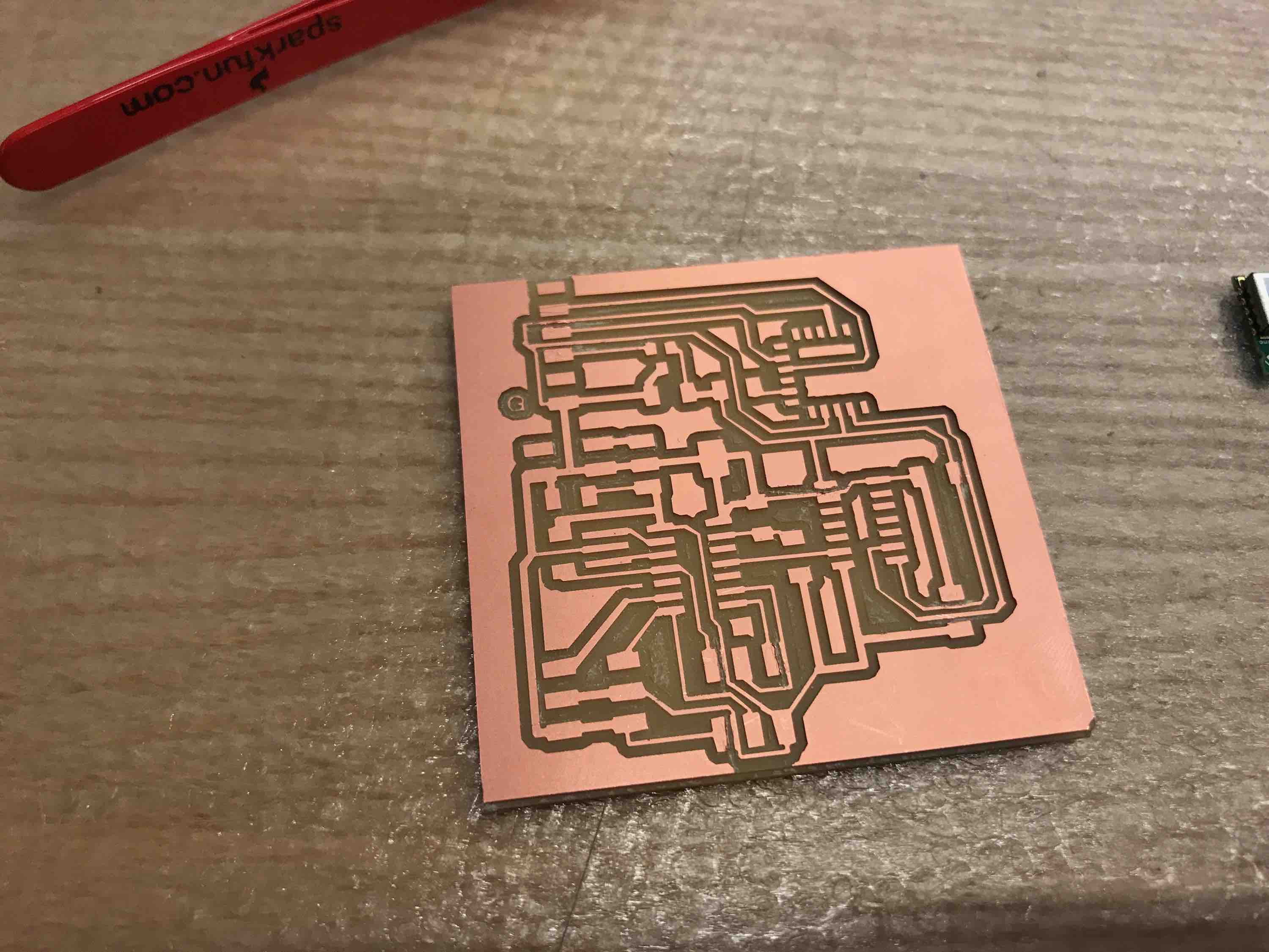
I had the same DPI doubling issue on the SRM-20 as before (150DPI -> 300 DPI). The end cutout had a few areas that weren’t separated, so I had to use a scalpel to etch it out manually.
Bending the pin worked ok:
Lab ran out of 22uF capacitors, so I had to stack 3 capacitors in parallel to get 21uF (I reckon this is close enough to 22uF).
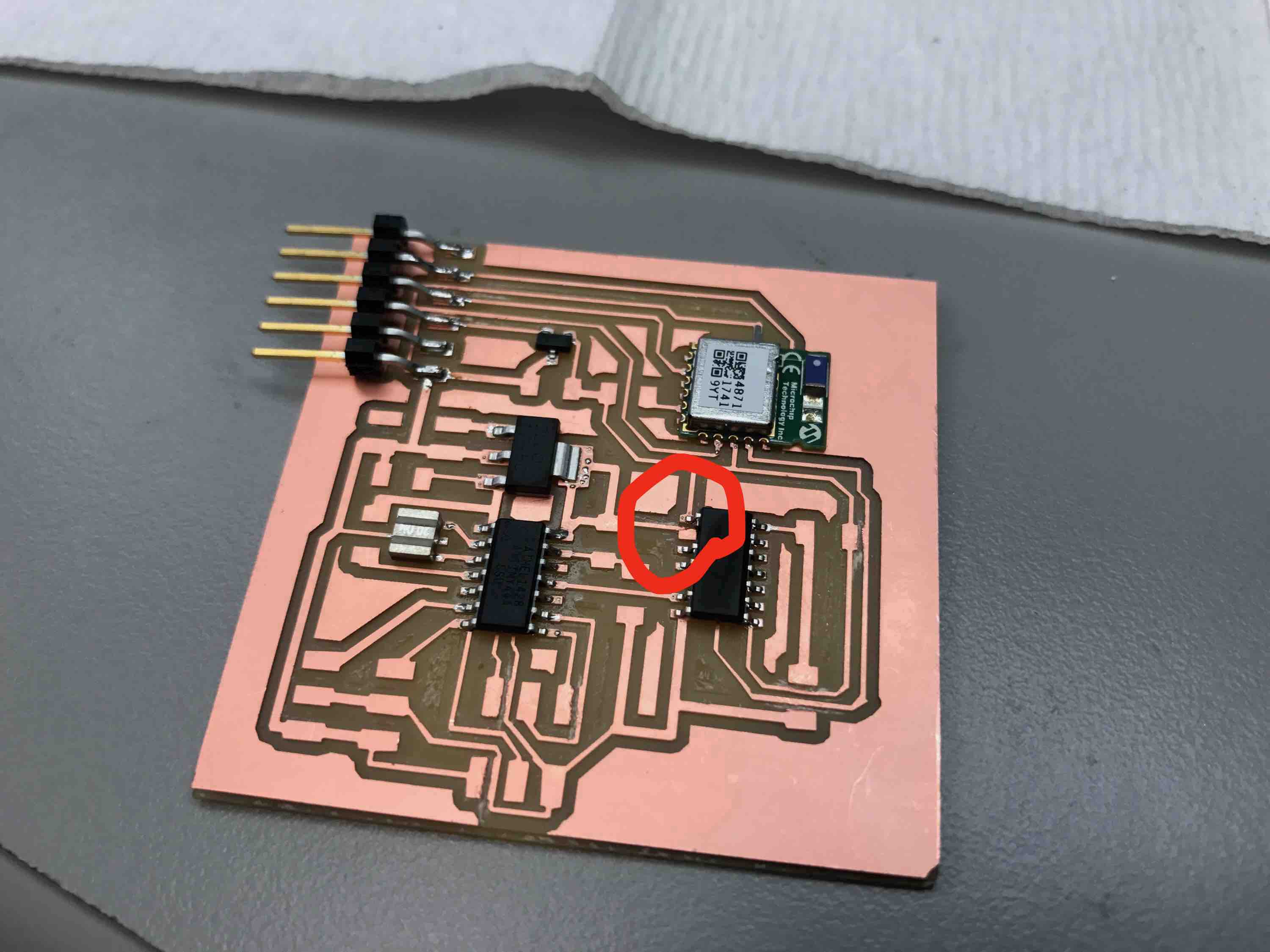
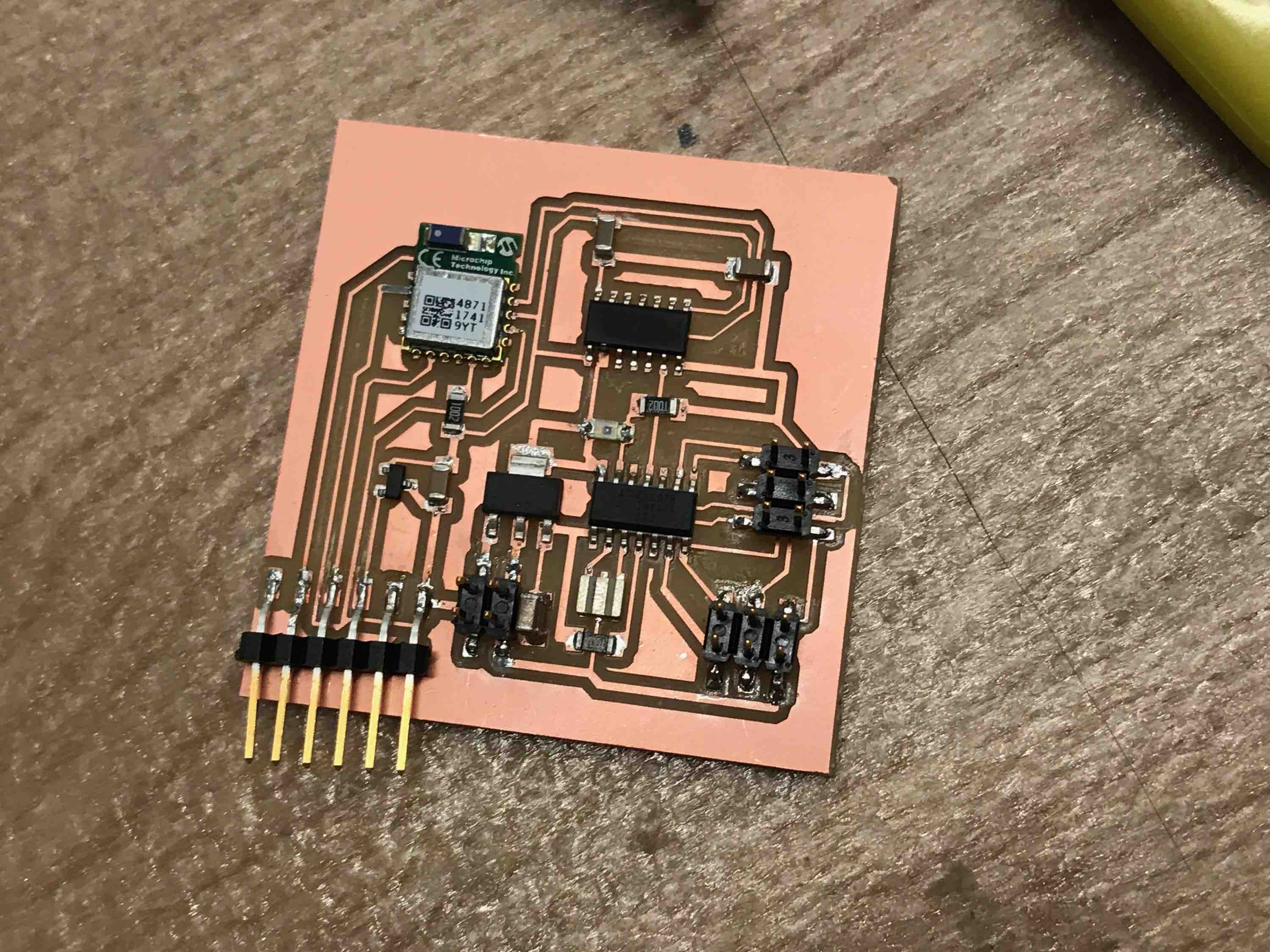
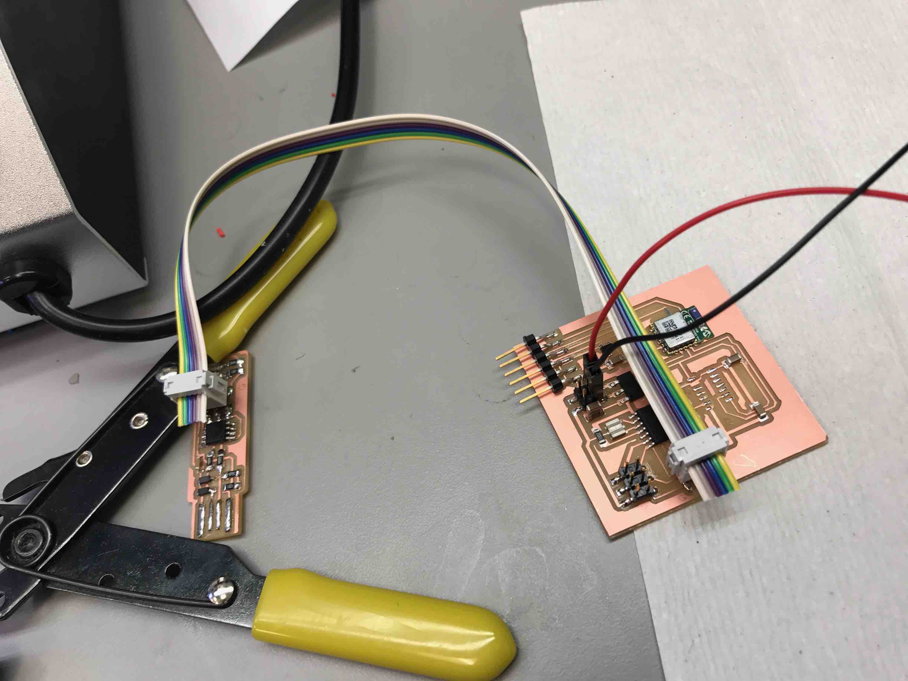
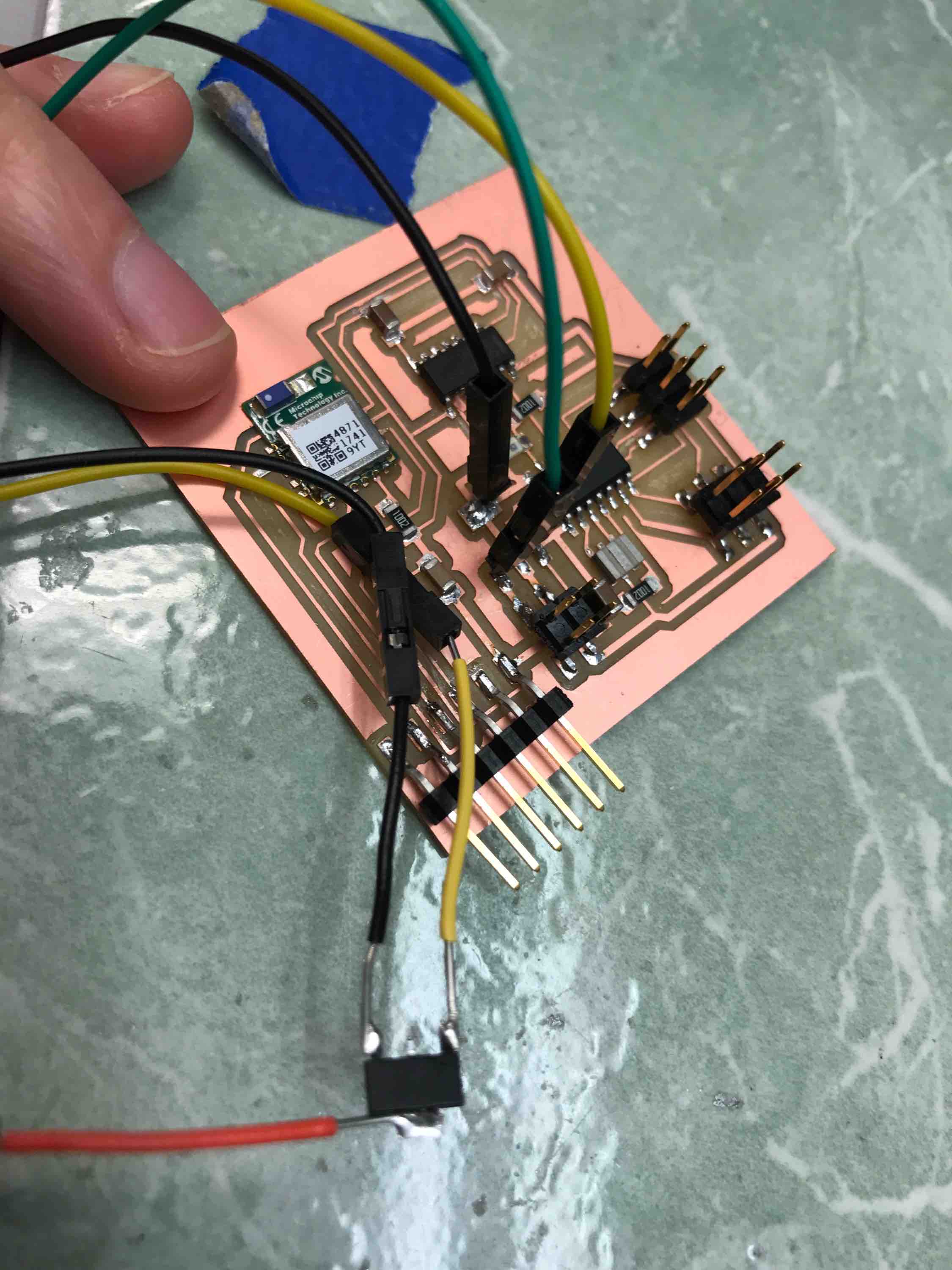
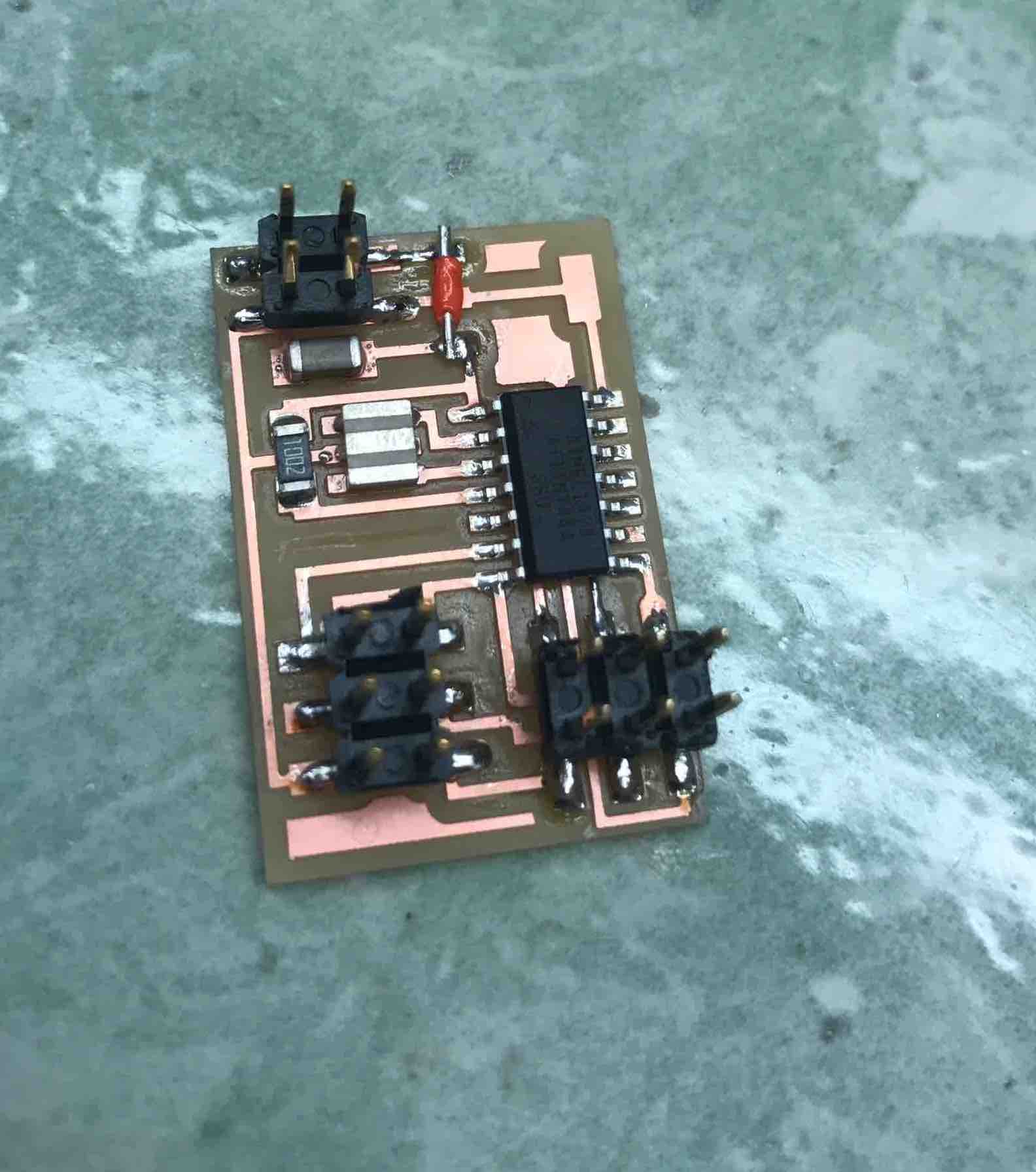
Final board:
Programming BLE
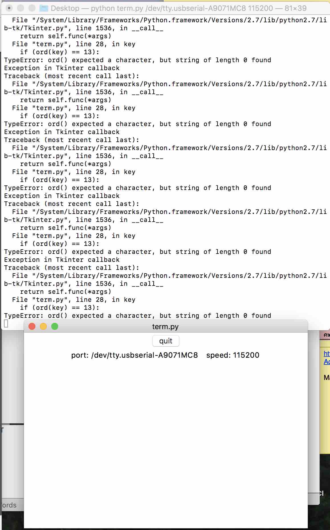
To program, I downloaded term.py from http://academy.cba.mit.edu/classes/input_devices/python/term.py. It was difficult at first to find out how to connect to my board, but I figured out that I had to do "python term.py /dev/tty.usbserial-A9071MC8 115200". To get the /dev/tty.usb… I had to TAB to auto-complete. The 115200 is the default baud rate from the RN4871 user guide ( http://ww1.microchip.com/downloads/en/DeviceDoc/50002466A.pdf)
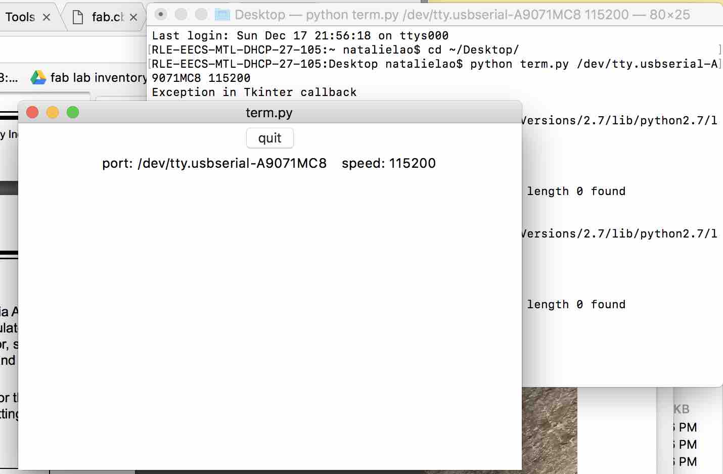
After running the “$$$” command to enter command mode on the board, I couldn’t get the board to respond to getter commands. Eventually, term.py threw this error:
This did not work, so I tested it using the short circuit/voltage measurement device. I found that the voltage regulator was sending power at 3.3V but the RX line was shorted to ground. I used a scalpel to clean up the traces a little.
I THEN TRIED USING MINITERM AND IT WORKED: python miniterm.py /dev/tty.usbserial-A9071MC8 115200
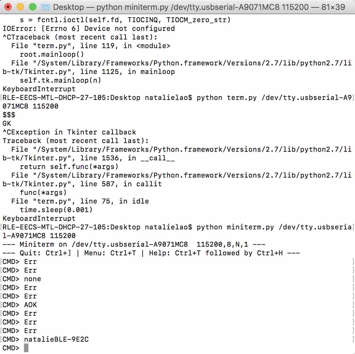
I successfully named my board natalieBLE. It’s a little annoying that you can’t see what you are typing in. EDIT: If you press “+”, this will show you what you are typing.
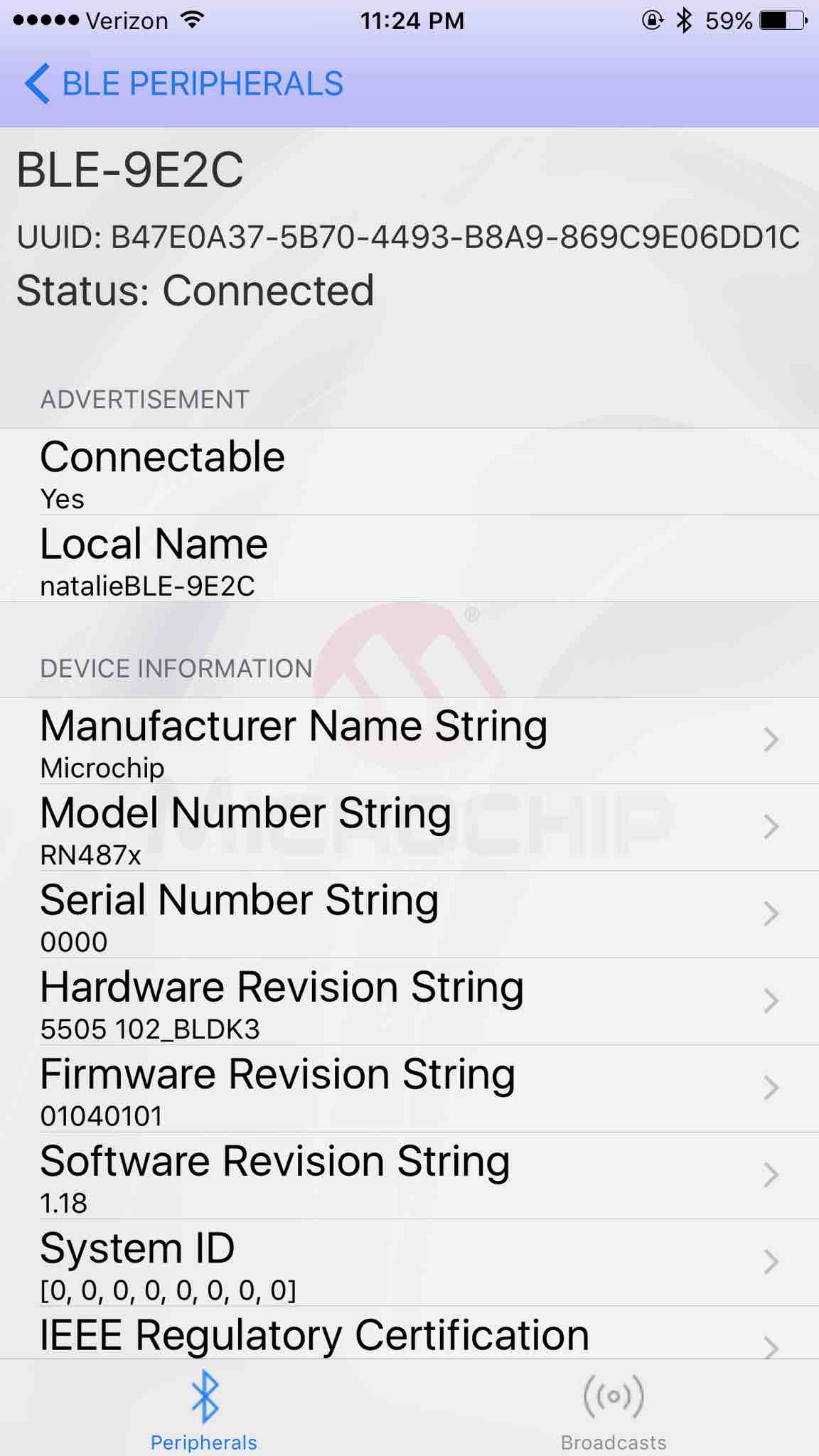
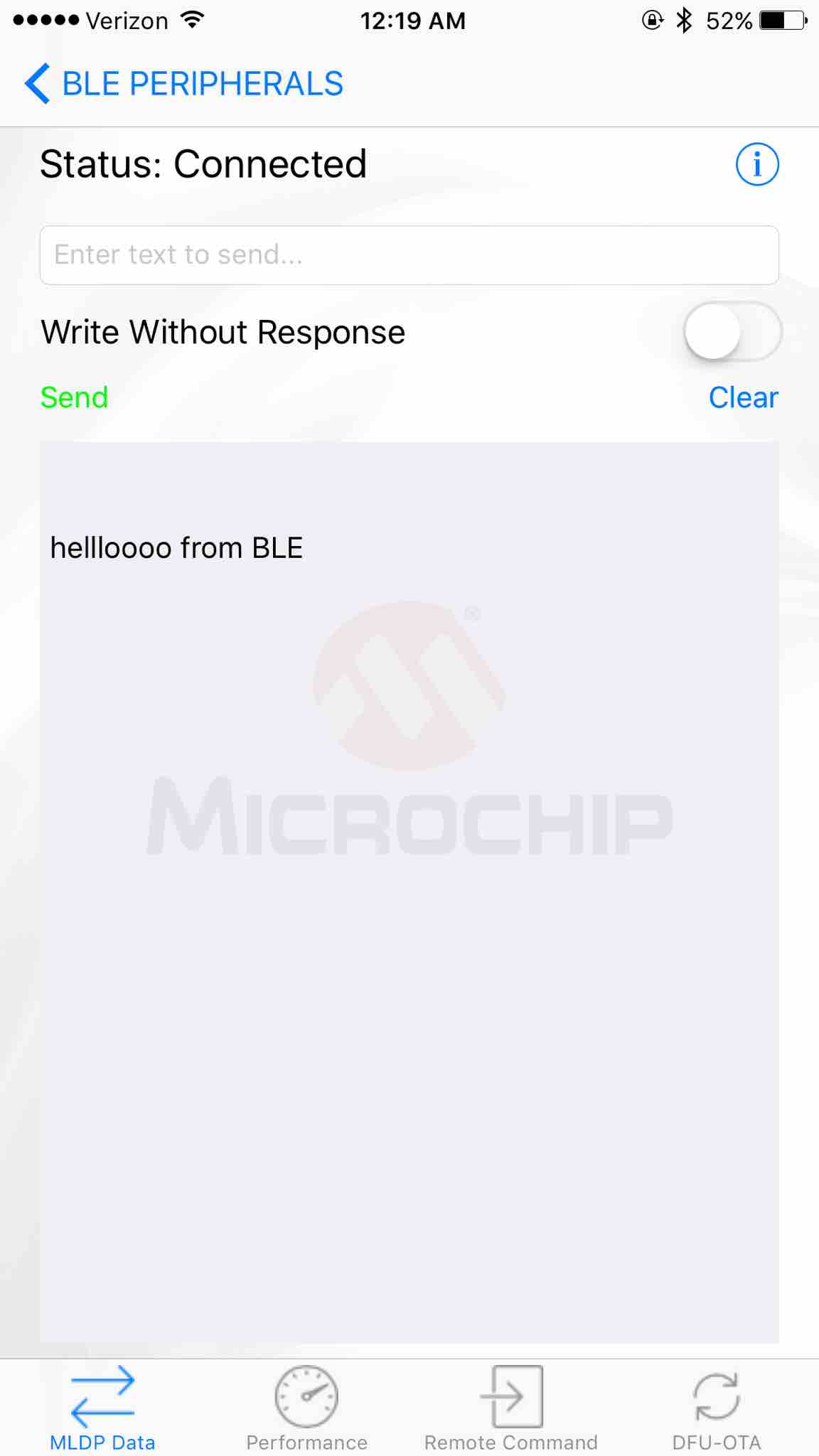
I downloaded the Bluetooth Smart Data app as recommended by the RN4871 user guide: https://itunes.apple.com/us/app/bluetooth-smart-data/id1004033562?mt=8. Then I sent “SS,C0” command to enable BLE transmission (Casey Evans helped me with a lot of the commands since she is also using this board). The board showed up in my app!
The Smart Data app supposedly lets you send and receive messages. First, I enable RN4020 MLDP streaming service by entering the command: “SR,0020”. I also entered “I” to start the service. The Smart Data app lets me send messages to my device.
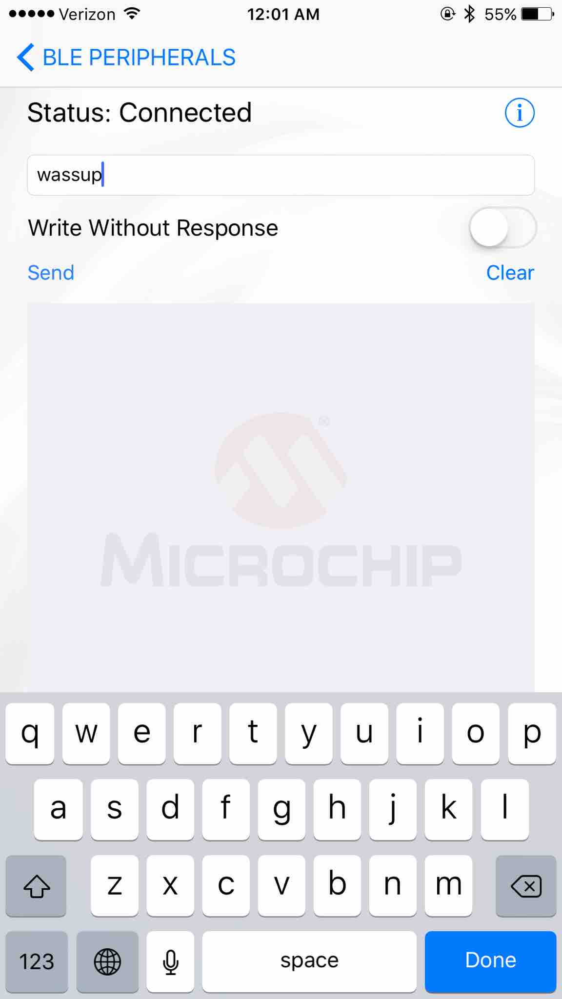
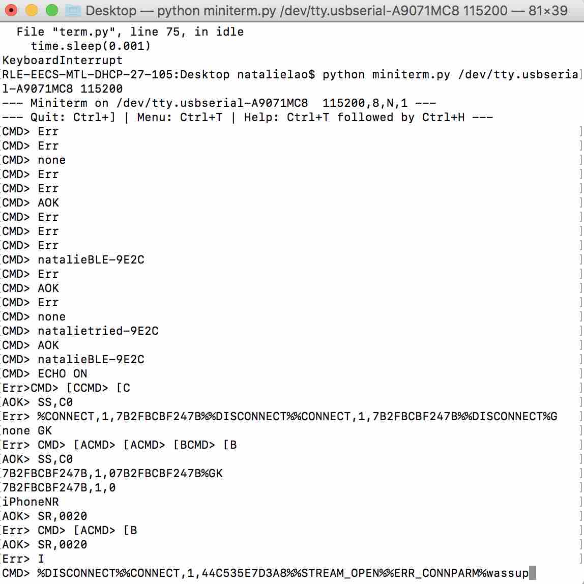
I also can receive messages from my BLE when I type to it from my computer:
Remote command mode looks useful (2.6.4), as well as section 2.6.7 “|O,
Programming Motor and Light Sensor
To remember:
- Brown = GND, Red = V
The voltage translator went up in smoke after a few seconds of connection to power. I removed it to continue debugging.
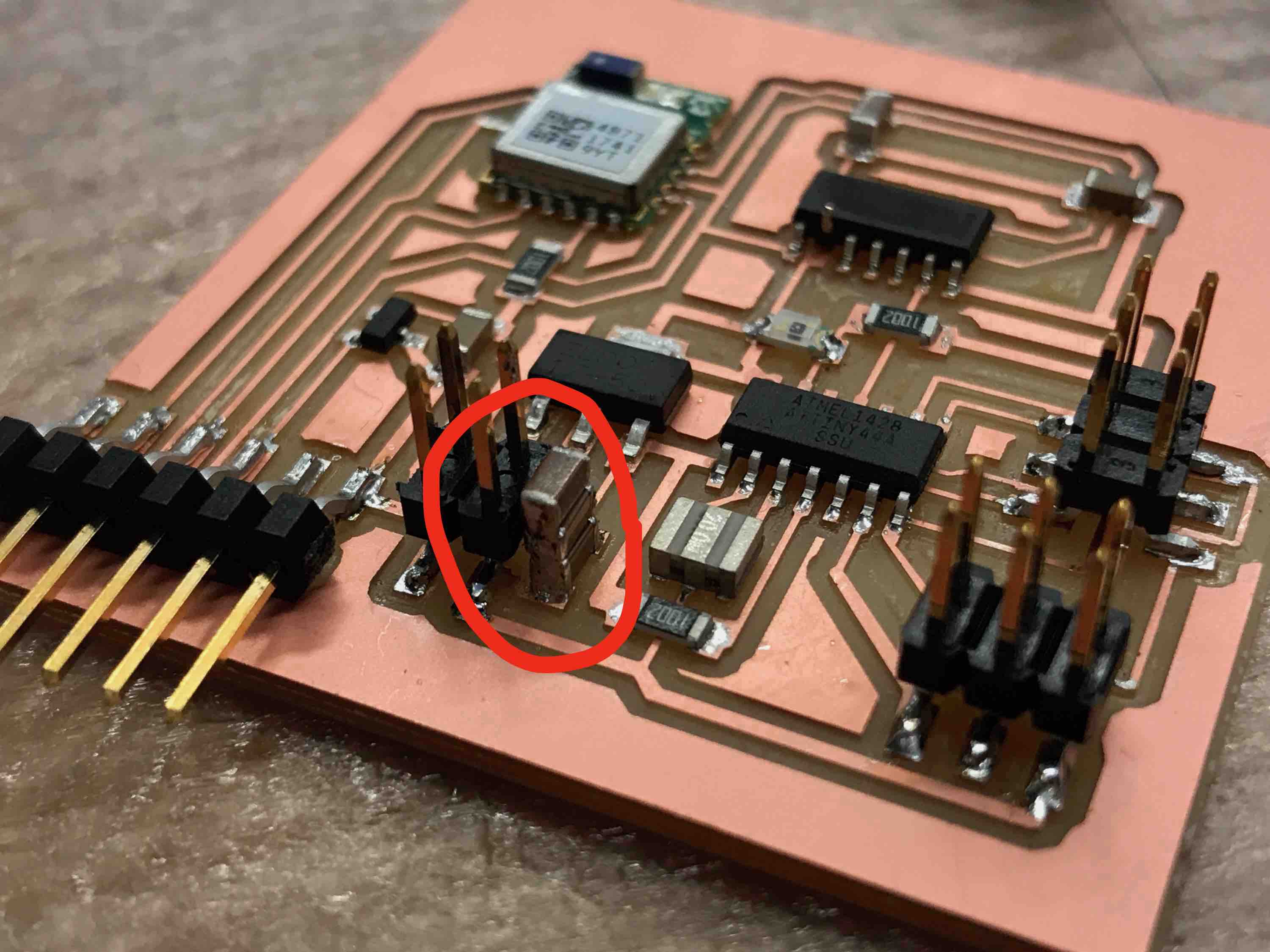
AFTER HOURS OF DEBUGGING, BEN HELPED ME FIGURE OUT THAT THE 5V VOLTAGE REGULATOR I USED WAS MISMATCHED TO THE ONE REFERENCED BY NEIL. Even though they look identical and share some part numbers, their pins are swapped, which wrecked havoc on my board and burned my chips.
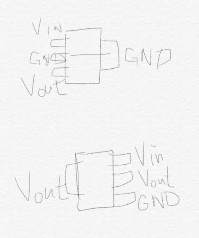
I based the motor part of my board off of Neil’s dual servo motor board design, which uses a large 5V regulator that looks exactly like https://www.diodes.com/assets/Datasheets/ZLDO1117.pdf (another 5V regulator currently in inventory with similar name) but an older version that has the pins in different orientations. This almost certainly caused lots of problems in my board. I had to replace the ATtiny, the VREG, and the voltage translator.
I fixed it by adding single headers:
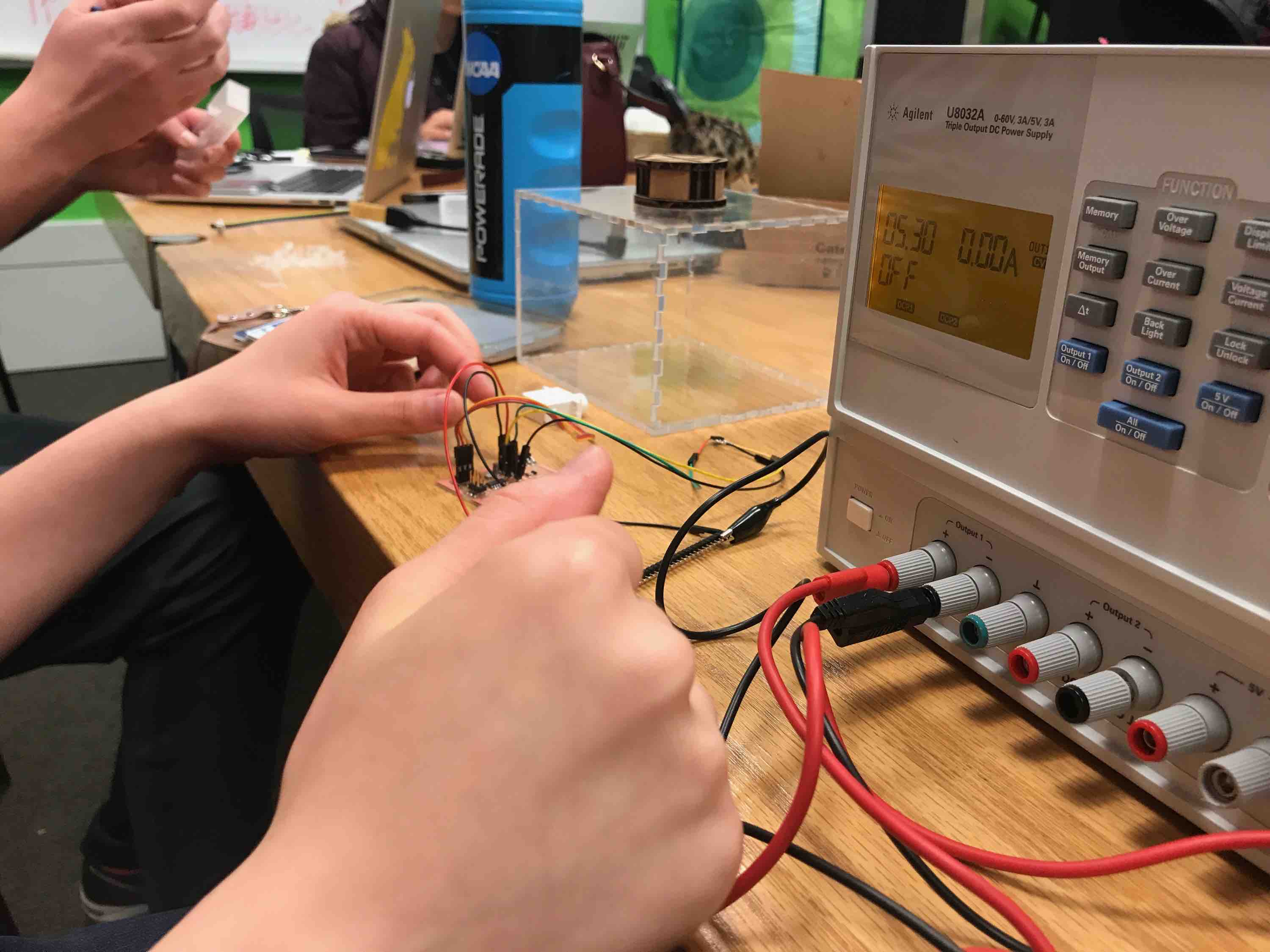
For programming the motor/sensor side, I used a combination of Neil's light sensor code and dual servo motor code so the servos are triggered to move back and forth between 90 degrees and 180 degrees when the resistance from the photoresistor/light sensor is low (resistance decreases with more light). I tested this by putting the photoresistor under the microscope lamps in EDS. I did the following:
- 9V battery or 5V power supply
- make -f hello.servo.44.make
- This should generate a hex file and an out file (cat hello… to check text)
- I should then be able to call the programs in the make file directly. (This requires avrdude)
- Program-usbtiny should be the one I call
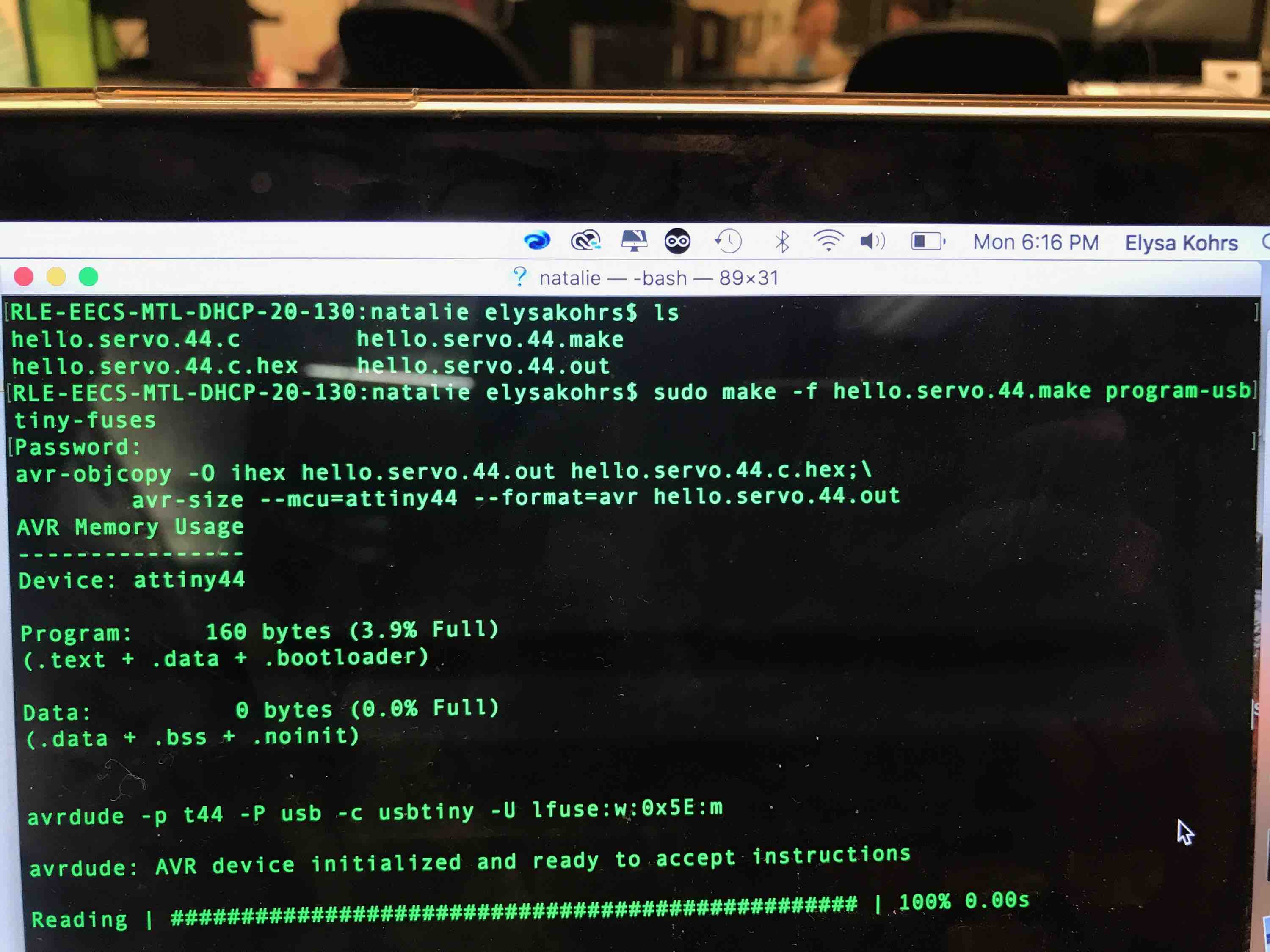
IT WORKED! I am able to run Neil’s photoresistor code, accounting for the different pin mapping. Powering the RN4871 BLE chip and the ATtiny44a (running the photoresistor and motor sides of the board) allows the voltage translator to receive input from the ATtiny. I originally wanted the BLE to give commands to the ATtiny, but I would need a UART pin for that. Currently, my board is not made to switch UART pin function from programming to communicating via the 3.3-to-5V voltage translator, so I will be satisfied with just receiving the signal from the voltage translator. I'm still trying to figure out what value cutoffs correspond to high light vs. low light.
It stopped working after an hour or so of programming/testing… Gavin said that it might have been due to weird parasitic interactions when the programmer and motor are both plugged in. I made sure the programmer and motor were never plugged in at the same time and then ran my code. This worked for a few seconds and then the power supply errored out. I tried to debug it for a long time after that and replaced several components, but it wouldn’t work even so…
I’m just going to try to make a simple motor board at this point from Neil's dual server board:
Board works with program-usbtiny-fuses and then program-usbtiny. I coded two servos to spin in 45 degree increments so the balls can be released programmatically. I then cut another lid to my box for securing the rotater: 0.4 inches by 0.125 inches for the tab holes and 0.4 inches by 2.25+0.125+0.125=2.5 inches (just above the height of the top rotating piece to secure the motor). I also made a stand for the bottom rotating piece that is 2+3/8 inches tall. The motor is 1 inch at its widest. Here is the C software PWM code and the makefile.
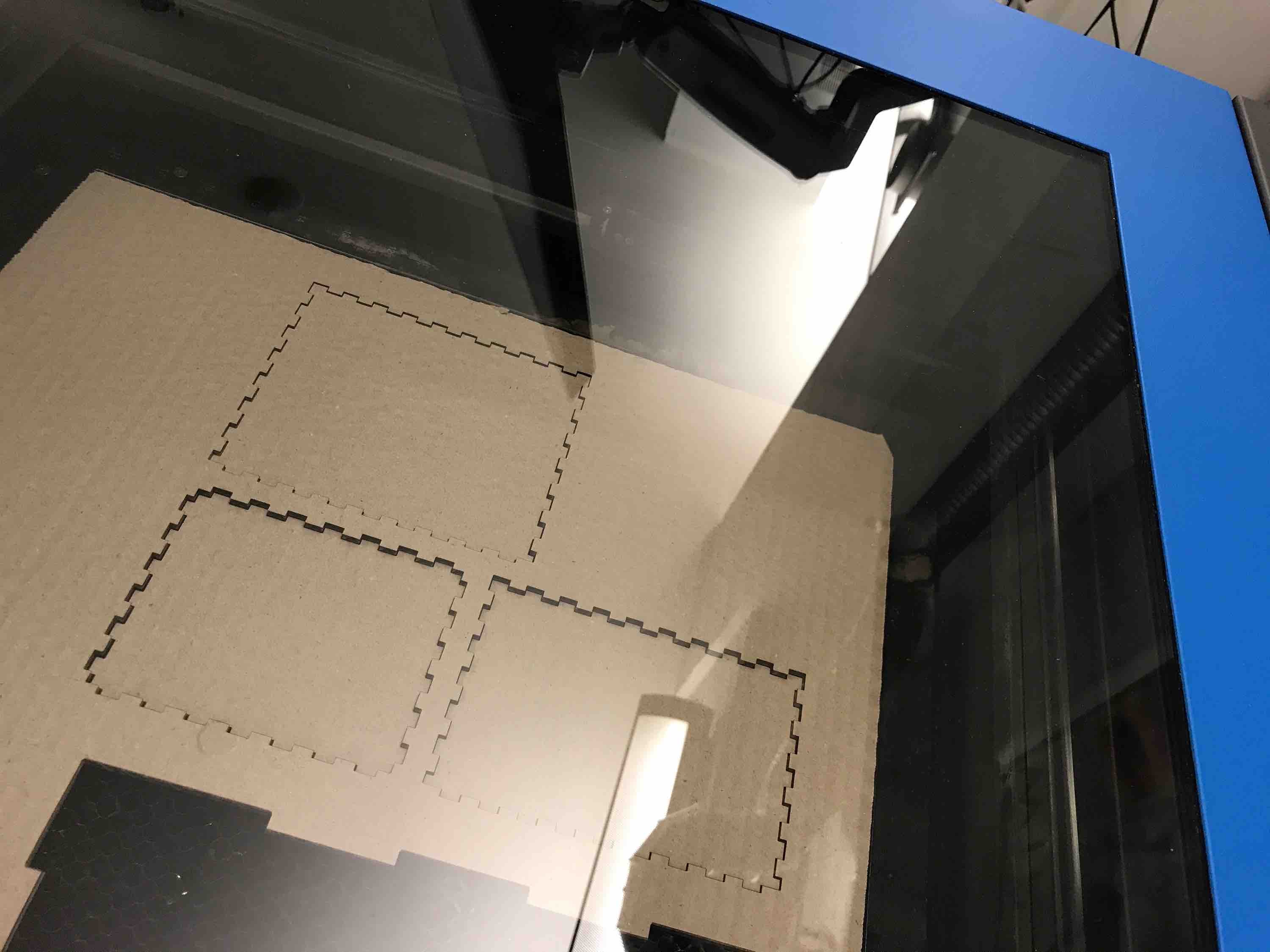
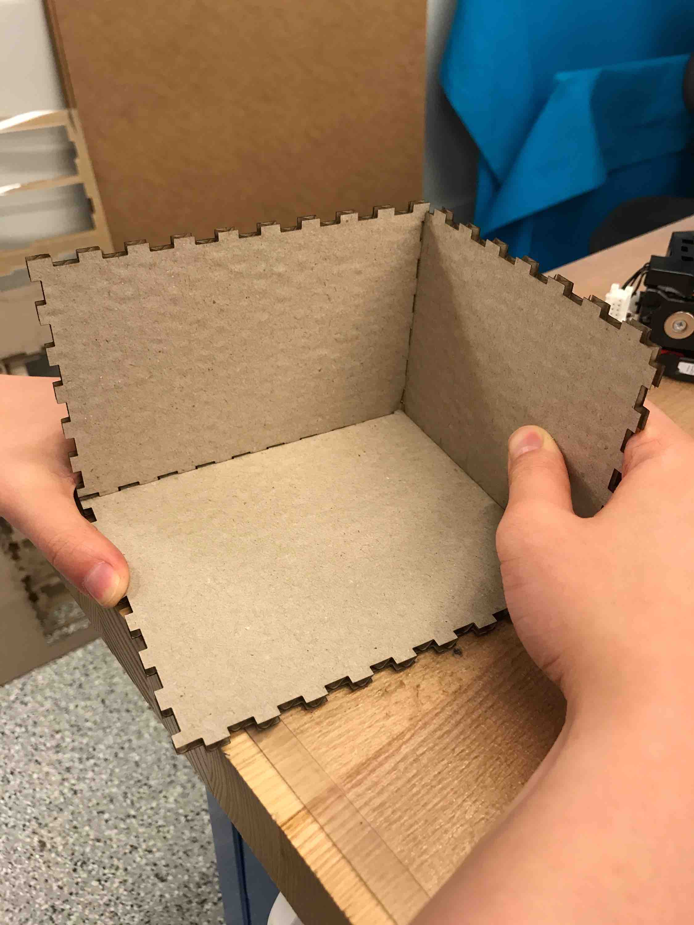
I made a standalone box to hold the ball (candy) ejector for when it is not connected to the ornithopter. I got a 4 in x 5 in x 6 in PDF design from the box designing website: http://boxdesigner.connectionlab.org/. I first tried out my design on cardboard to verify that it works:
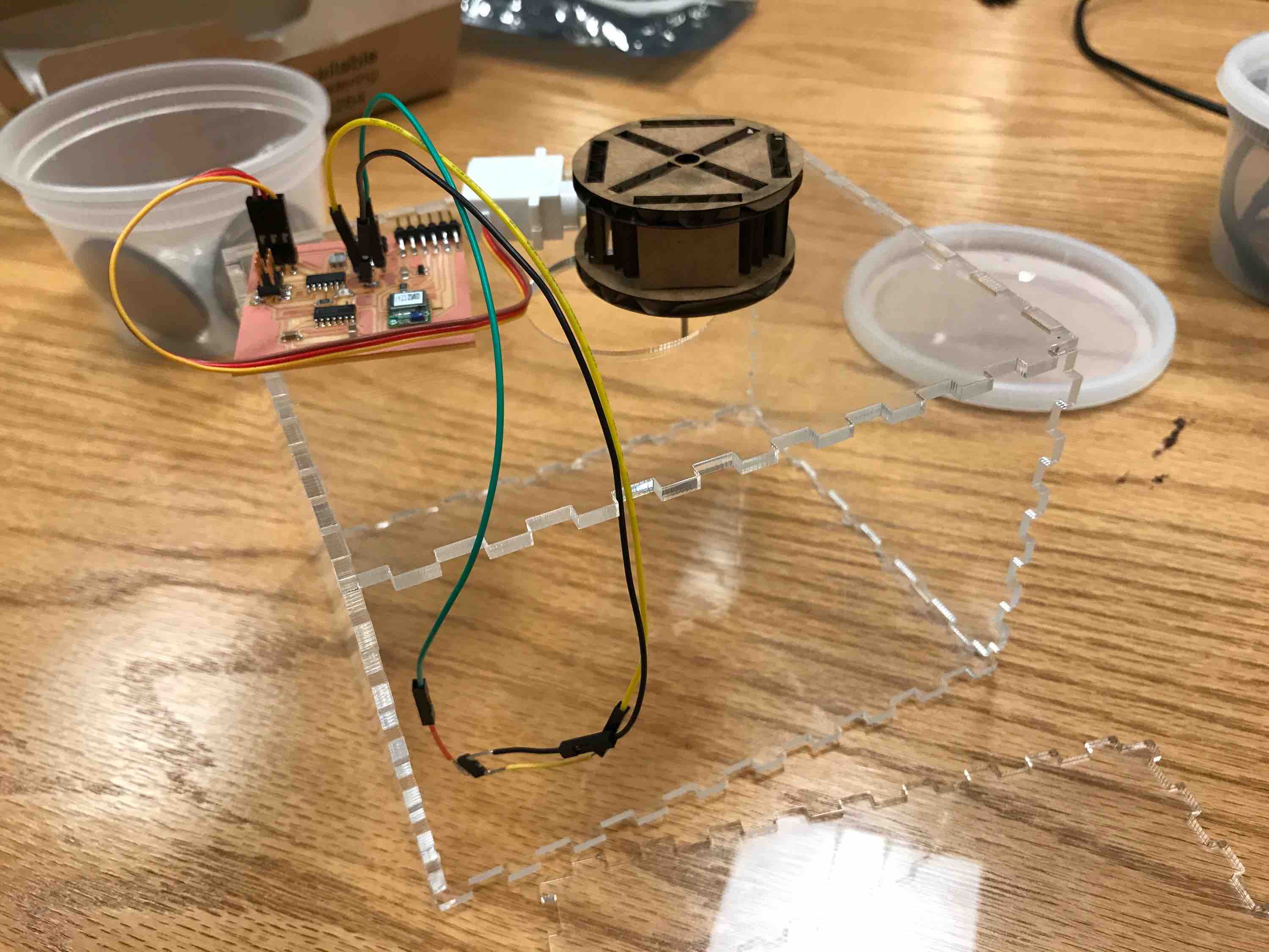
I then used clear acrylic to make sure you can see inside. I then milled a circle slightly smaller than the size of the rotor (2 inches in diameter to 1.7 inches in diameter.) It all comes together quite well – I hot glued together all of the panels except the top and the side panel for each removal/debugging.
Here it is working with my Oomoo balls:
The Oomoo balls were very bouncy and hard to work with (I lost one) so I decided to do the rest of the fixturing with wire balls. The hardest part was making sure the two servo pieces were aligned corrected in X, Y, and Z axes. With my original one-servo design (the one we are using for the ornithopter ejector), this is not very hard, but with two rotating circular surfaces that have to remain parallel, it gets challenging because if it is off by one or two degrees, the pieces will clash and fail. Here is the working final fixture with wire balls:
Interfacing with the Ornithopter
As demo'd during final presentations, the pooper interfaces with the ornithopter and can run while the ornithopter flaps its wings from the same power source. Alex and I coordinated beforehand to minimize the number of connections that would have to be made. I modified the pooper device that went on the bird so that the hole piece is fixed to the top of the board and so only one servo motor needed to be used to spin the ball-holder piece. I laser cut some basic cardboard to make this fixture (press-fit) and used hot glue to stick it to the bird.
The chip in the video is my final board chip with the photoresistor and the RN4871.
Bill of Materials
- Hobby King HKSCM9 Digital Micro Servo x3 = $3.22 * 3 = $9.66
- 1/8 inch clear acrylic sheet around 12 in x 12 in = around $10.00 on average
- RN4871 chip is $8.44 from Mouser
- ATtiny44a is $0.72 on Microchip
- TXS0104ED voltage translator is $2.34
- Small single-sided copper PCB averages around $10
- Machinable wax block ~$16
- Resistors, capacitors, and headers are several cents to around $1 each, so approximately $5 for all that were used