Week 9: Output Devices
Designing the Electronics for a Quadcopter
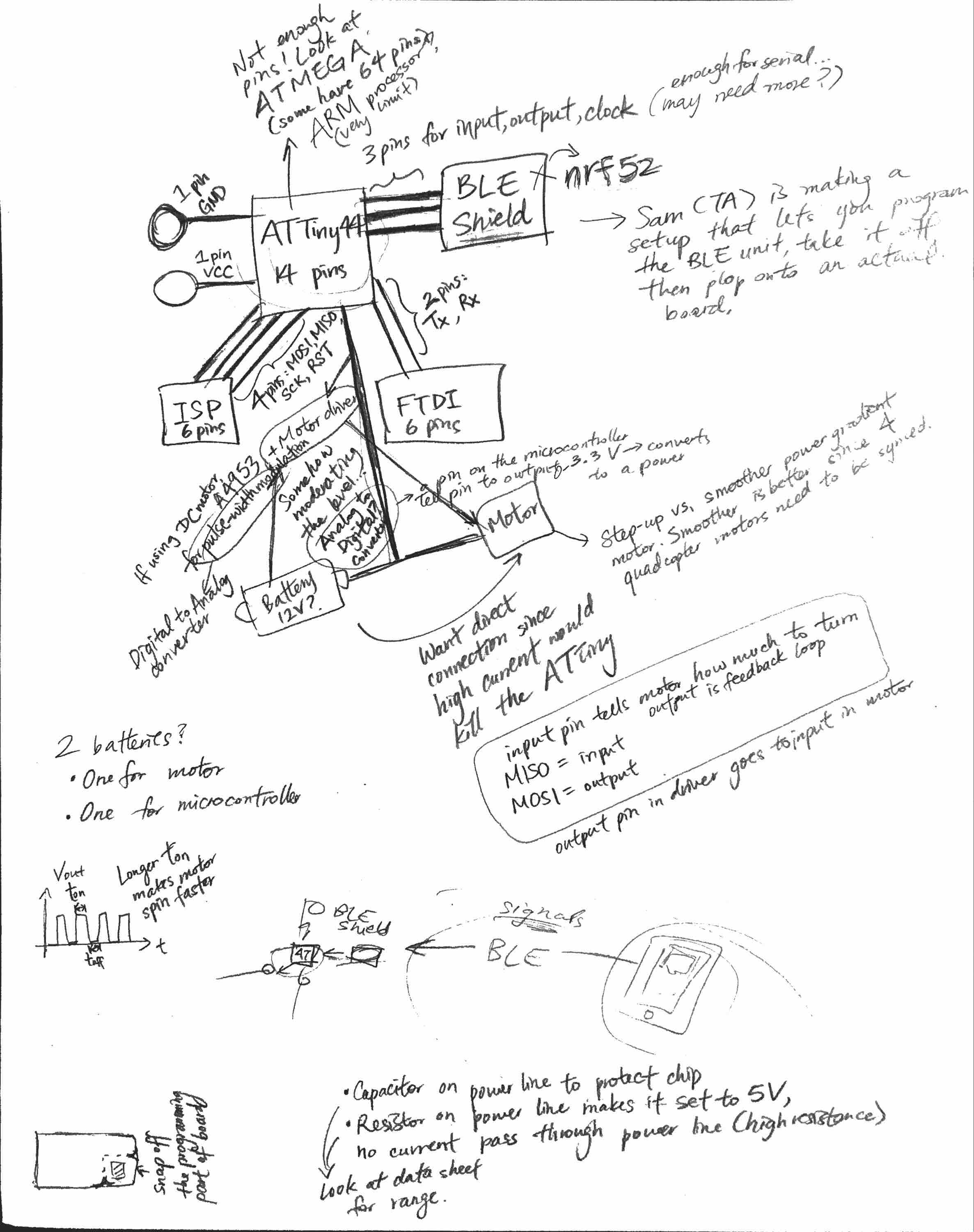
I wanted to add a motor as the output device to my board to make some progress on my final project this week. I initially wanted to start from the board that I had made for Week 7 with the button and the LED, but while looking at the data sheets for the DC motor and driver, I realized that my old board would not have enough room for the required motor and motor driver. So, I would need to design and fabricate a new board. I thought that in order to streamline the board fabrication process and decrease the number of new boards I would have to design for each successive step of my project, I would try to spec out and design the entirety of my electrical components first. This would involve:
- Microcontroller
- BLE unit connected to microcontroller
- Microcontroller connected to motor driver
- Motor driver connected to motor
- Battery with direct connection to motor driver
I tried to figure out the exact pins that need to be connected and other specific values and components by reading online tutorials and component data sheets. From this preliminary research, I gained three important pieces of knowledge:
- I should connect my BLE unit with my microcontroller using 3 pins for input, output, and clock (to make sure the clocks on both chips are synced)
- The battery (probably around 12V) should directly feed into the motor/the motor driver instead of through the microcontroller so that it doesn't burn out the chip. The microcontroller and motor driver should just act as a gauge to limit the amount of current that flows from the battery to the motor.
- I need some sort of Digital to Analog converter for translating the motor values from the microcontroller into signals that can power the motor.
I then went to Office Hours to figure out the specifics of how some of these modules should be implemented. Shirin was super helpful in explaning some of theory behind the signal processing required for my project and gave me lots of helpful advice:
- I was initially planning on using the ATtiny44 that I had been using for my previous boards, but Shirin mentioned that the 14 pins on that microcontroller were probably not going to be enough for talking to a BLE unit and four motors. She recommended that I look at the fab lab inventory for boards with more pins. From that list, I found that the ATMEGA328P, ATxmega16E5, and ATMEGA16U2 had 32 pins; and the ATMEGA16U4 and ATxmega16A4U had 44 pins. I may also look into ARM processors, but I may not need something that powerful.
- I was initially going to use a BLE Shield module for my BLE component, since a lot of the tutorials I found online mentioned a BLE Shield and I found something similar in the fab lab inventory. Shirin recommended that I use a nRF52 instead and also mentioned that the TAs were going to make a BLE programmer that students could use to program their BLE components, remove them from the programmer, and attach to their boards - essentially, I would not have to build in a separate system to program my BLE module onto my board (which I needed to do for my microcontroller with adding the FTDI and ISP units).
- Shirin helped explain pulse-width modulation with DC motors to me. I learned that the motor driver converts some "motor speed" signal from the microcontroller into a sequence of pulses to send to the motor, which will actually make the motor spin at some constant speed. A longer t_on in the pulse-width modulation graph results in the motor spinning faster.
Here is the main page of notes that I took for designing my electronics:
