Week 7: Embedded Programming
Reading Data Sheets
While doing the Week 5 assignment of designing my own board, I had already looked at the data sheet for the Atmel ATtiny44. I was originally going to add a pull-up resistor between VCC and the button input so that the current can flow through normally when the button is pressed and so that the voltage doesn't float when the button is released, but then I read the data sheet and realized that both Port A (PA7:PA0) and Port B (PB3:PB0) have internal pull-up resistors, which means that I could program the microcontroller to substitute for that task - I ended up just putting the button between PA7 and ground. I had also looked at the data sheet to figure out which pin was GND for orientation purposes. I had also looked at the data sheet for my red LED to figure out the polarity (the line was the anode).
Writing Code
I slightly modified Neil's starter hello.ftdi.44.echo.interrupt.c code so that the LED would blink when you pressed the button. I set the pins connecting to the button output and LED input in the code as well (PB2 and PA7). My code is attached here. Below are screenshots of the relevant sections in the code (the pin setting and the main script):
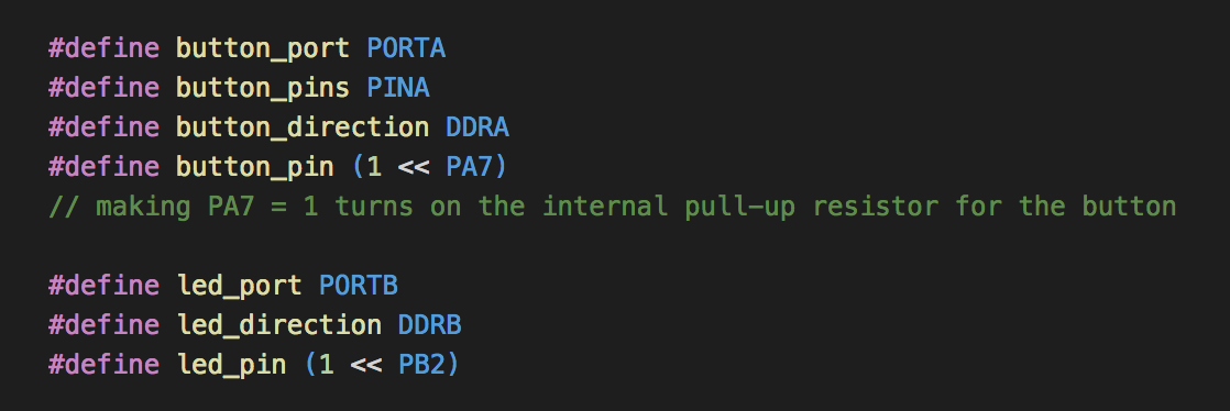
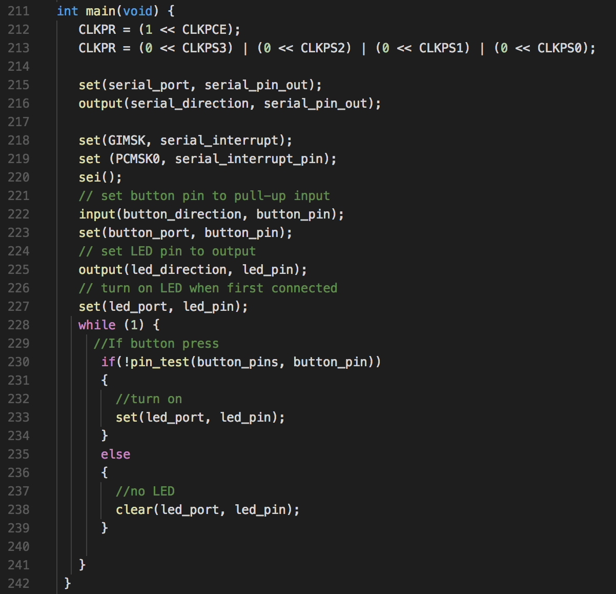
I've written C code before so this part wasn't terribly difficult.
Programming the Board
First, I downloaded the make file for the starter code: hello.ftdi.44.echo.interrupt.c.make. Here are the rest of the steps I took to program my board.
-
Set up the board and the connections same as last time (the programmer connected to the computer via USB and my new
board connected to the computer via a FTDI/USB cable)

-
Check to make sure that the computer recognizes the programmer (Multiple Vendors USBtiny) and the new board (Future
Technology Devices International...). I did this by running lsusb in Terminal.
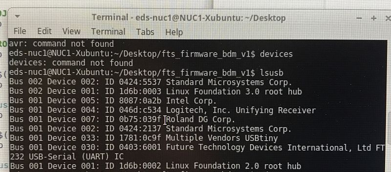
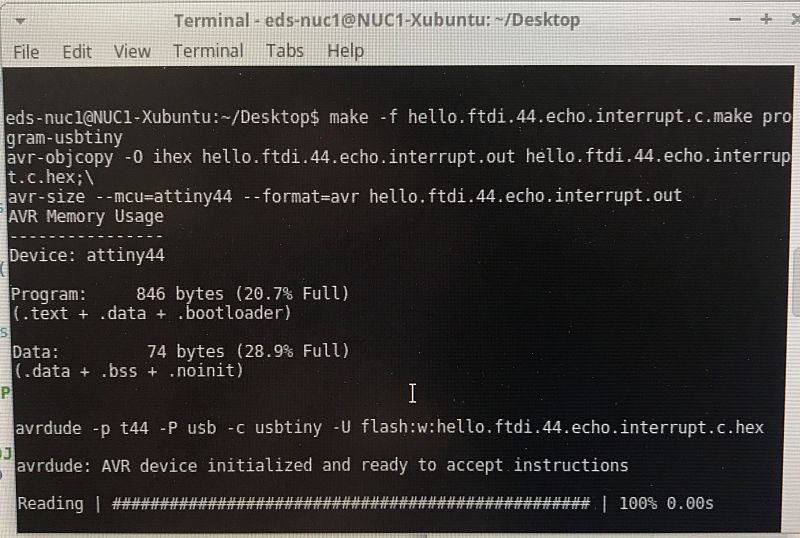
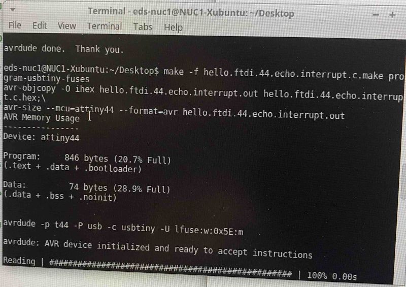
- Run make -f hello.ftdi.44.echo.interrupt.c.make program-usbtiny per the .c.make file. When that successfully finishes,
run make -f hello.ftdi.44.echo.interrupt.c.make program-usbtiny-fuses. Successful run messages will look like so:
-
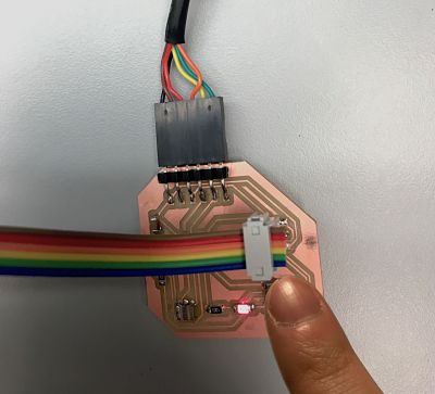
The code should now run on the board! A power cycle may be required (unplugging everything and then replugging):
I actually ran into some errors programming my board the second time. It would fail to load, displaying the message below:

The running hypothesis is that I was too rough with plugging and unplugging parts of my board and it made some connections too weak. I did extensive probing and tried to resolder the microcontroller, but it failed again. I think I may need to rebuild all of the components on my board if I want to make it work again.