Week 4: 3D Printing and Scanning
Group Project: Characterize Lulzbot TAZ 6 3D Printer
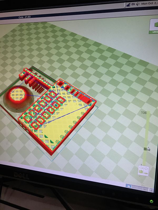
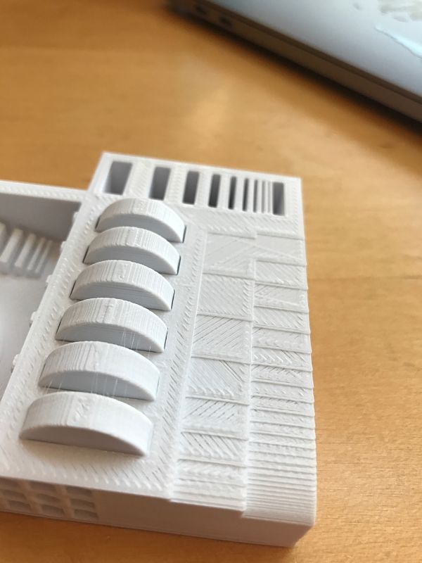
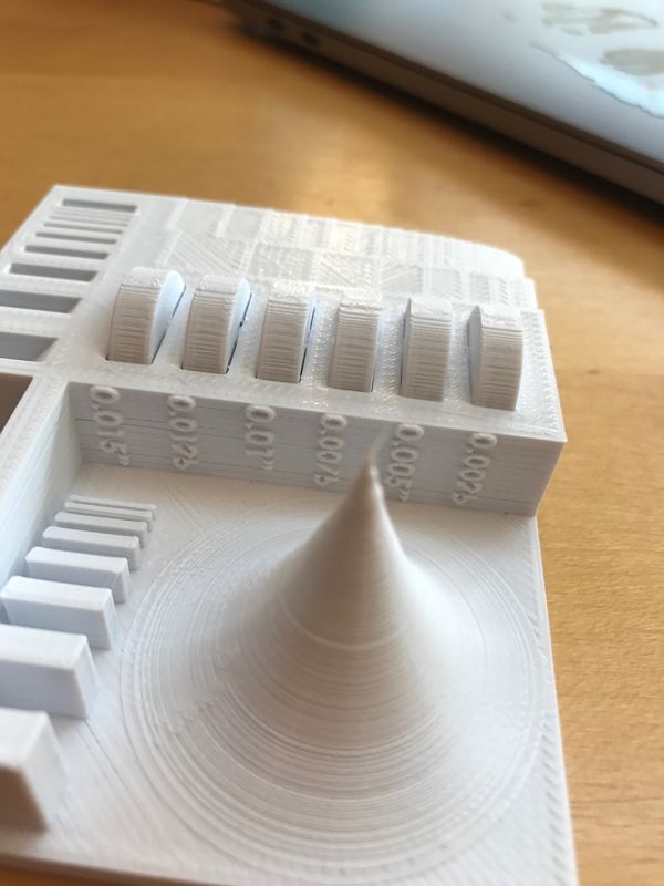
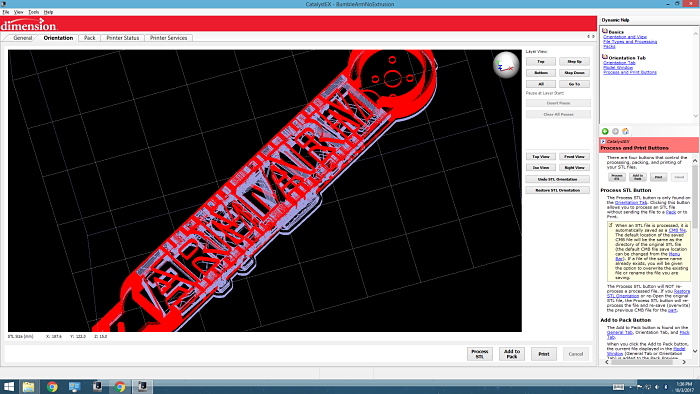
Ben and I characterized the Sidney Pacific graduate dorm 3D printer, which is a Lulzbot TAZ 6 using PLA filament. We used the 3D printer tolerance test model created by Amanda and hosted on Thingiverse. The Lulzbot also uses its own software called "Cura", which can be downloaded from the company website. The software is able to display all of the layers and tool paths in a controllable way as below:
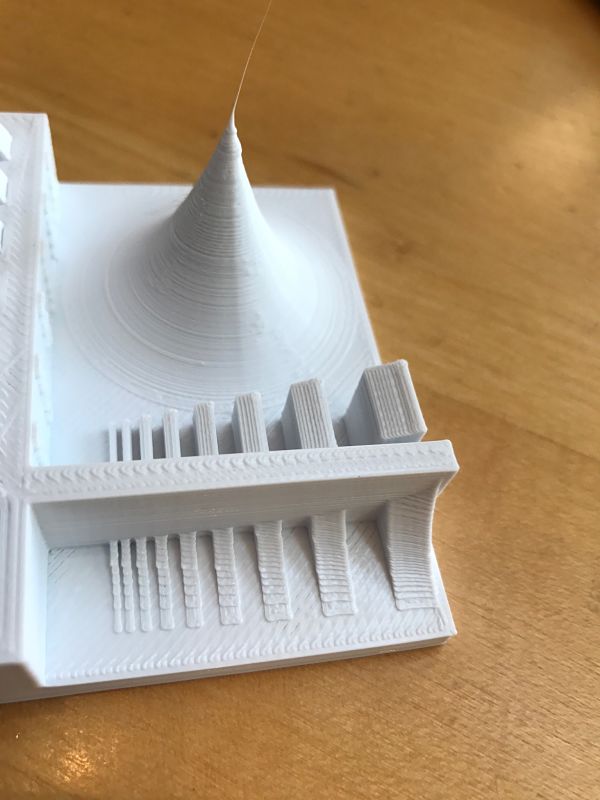
The print came out fairly precisely with some defects: (1) the discs did not spin since there was no support material between the disc and the center rod, (2) some of the last characters in the numberings were not fully rendered along the side, (3) the diagonal path that the printer head took along flat surfaces is extremely apparent, as most of the surfaces were diagonally wavy and not smooth. I had to remove the structure with a knife since the bottom board was not removable and the material was stuck too well to pull off.
3D Scanning with the Sense
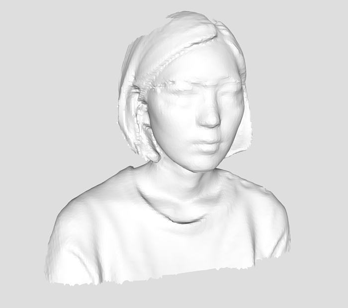
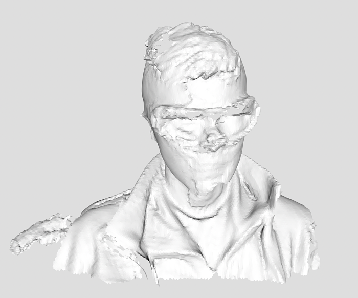
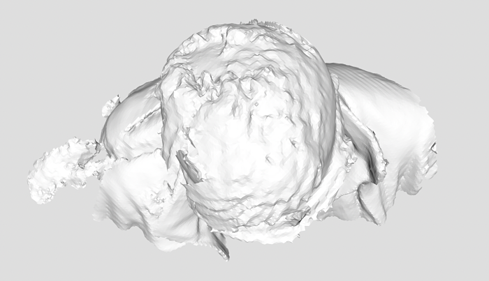
I used the Sense in lab to try to get 3D scans. I was generally unsuccessful. The tool seemed very delicate and often lost track of the object. I first tried to scan a ring, but it seemed to be too small to be picked up. I then tried to do the head scans. It was relatively easy to scan the front of a face (around 180 degrees), but getting the entire head with the back and top of the head was very difficult. See the first image below for an example of a front-facing scan and the second and third images for shots of a full head scan. The hair near the top of the head was oddly shifted, as was one of the sides of the face.
3D Printing Adventures
For this week's 3D printing assignment, I wanted to make some headway on my final project plans to make a quadcopter. I did some research into quadcopter designs and found that many makers had shared their quadcopter building experiences online. I found these sites particularly helpful:
- Propellers, Motors, and Multirotors for Quadcopters
- Tips for 3D Printing a Drone
- Example 3D Printed Quadcopter
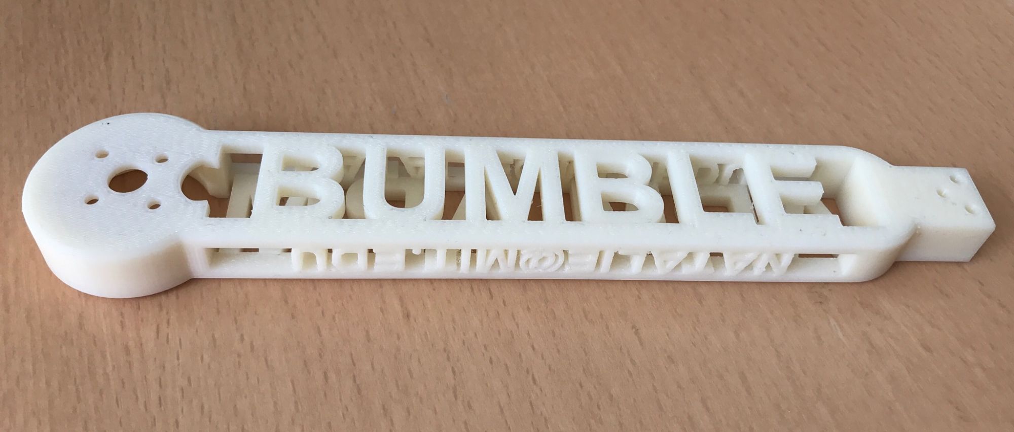
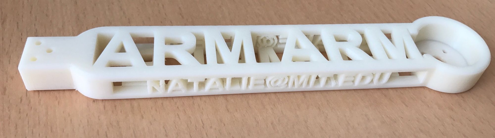
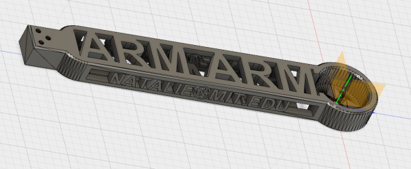
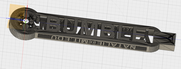
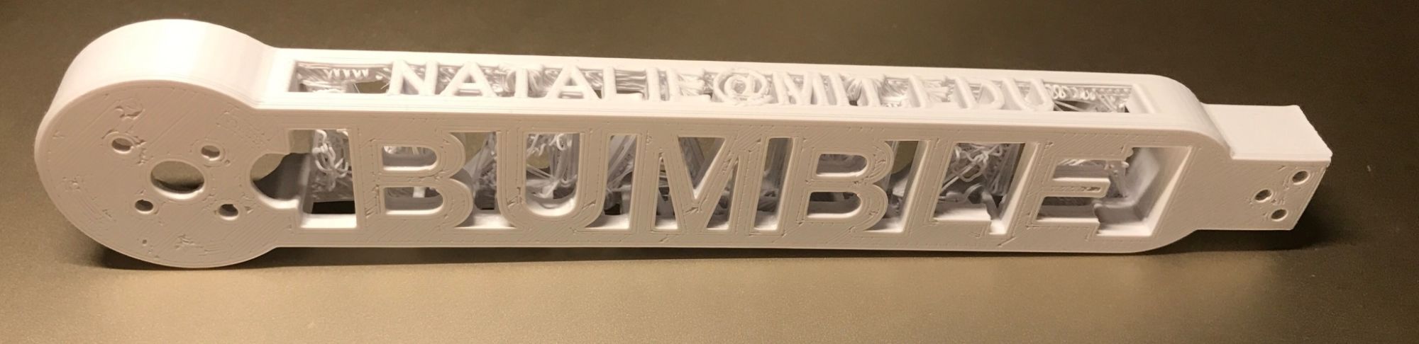
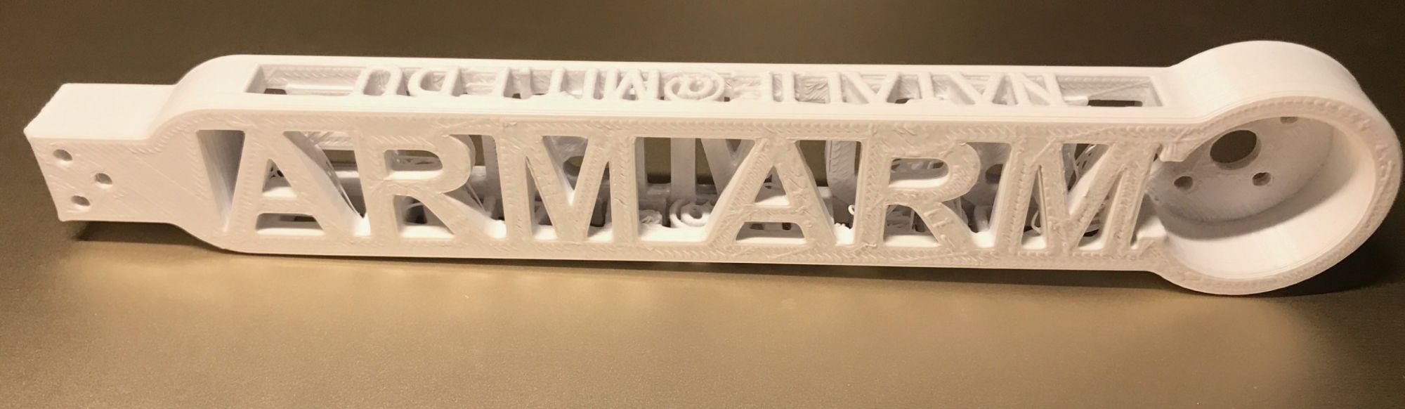
In order to fulfill the "additive" requirement, I made the main support structure of the arm a hollow rectangular prism with lettering along all four sides. The top reads "ARM" to identify the part, the sides read "NATALIE@MIT.EDU", and the bottom reads "BUMBLE", which is the name of my quadcopter. The circular pocket for the motor was designed to hold a 6cm motor. The entire arm was around 21cm. Some screenshots of my STL are below:
I initially tried to print my design on the Lulzbot without any support material, mostly due to the uprint machine always being unavailable. This started off pretty reasonably:
However, when the Lulzbot tried to print the top "ARM" layers of the object, the filament starte to sag and create imperfect birdnest-like strands in the middle space of the arm:
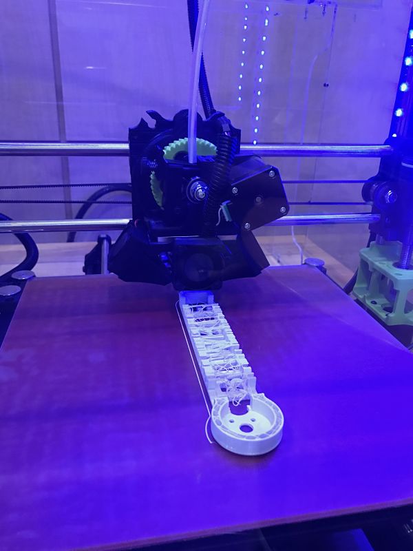
The final design was fine from the outside, but I was dissatisfied with the mess on the inside. Some of the letters of "NATALIE@MIT.EDU" also sagged. This took around 3 hours to print.
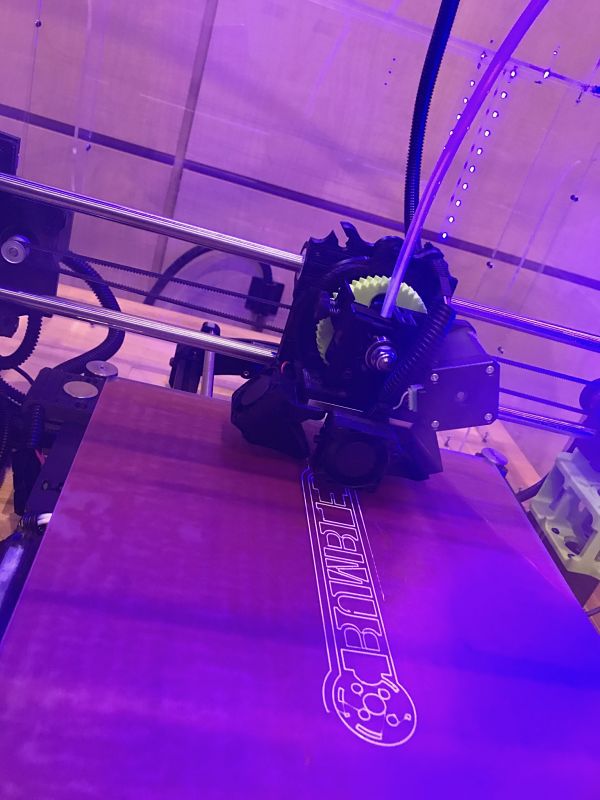
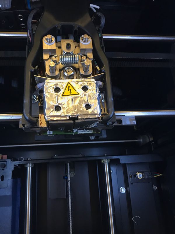
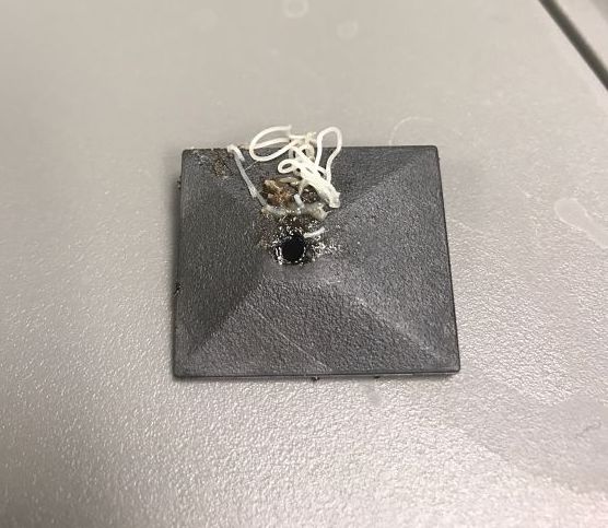
I went to lab several times to try to use the uprint 3D printer since it offers support material that can be washed away. However, the uprint was almost always already printing a job (as expected) and the timing did not match up for me to add my design to the pack. I finally got the 3D printer Tuesday night before class. Interestingly, the design started to bird nest after 2 layers. I noticed that there were a few clumps and strands of filament clinging to the bottom of the tool and asked for Dave's help. Dave showed me that the tip protectors seemed to be damaged and showed me how he changed them.
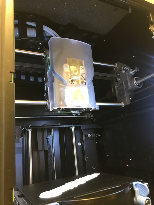
I plan to see how the print job turns out after class on Wednesday so that I can evaluate whether I should use 3D printing to create my quadcopter frame. As a preview to the final product, this is the toolpath for the filament and the support material on the uprint:
Update: I was very impressed by the result of the uprint. It took a little more than 5 hours to print and I soaked it in the support dissolving solution for 2 hours. Everything, including the inside hole portion, was almost completely clean. There were a few small pieces of support material that I had to pick off of the smaller letters on the side, but overall the design came out wonderfully. I did notice that this piece was noticeably heavier, duller, and smoother than the piece printed using PLA. This is probably because the ABS filament that the uprint uses is denser and has stronger material properties. I will need to do some stress calculations to determine the balance between structural integrity and weight for my quadcopter parts. A TA also suggested that I rotate the rod portion of my arm design so that the longer width is pointing down and the weights at either end can be better supported.