Xin Wen
Week 9: Output Devices
double check the datasheet!
1. Fabricating the Servo Board
2. Making the RGB Board
I started with Neil's servo board to understand how PWM works. For my final project, I need to display light of different colors to express user's mood, so I thought about using RGB LEDs which requires PWM.
1. Fabricating the Servo Board
I started with the example servo board (traces, outline).
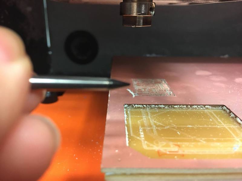
Figure 1. The end mill came loose and the tip broke off.
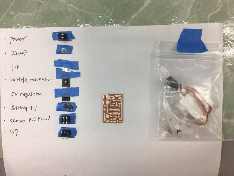
Figure 2. Fabricated board and components needed.
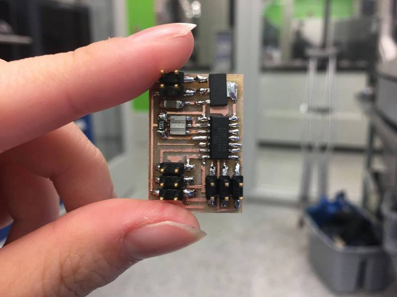
Figure 3. Soldered (much faster than previous attempts)!.
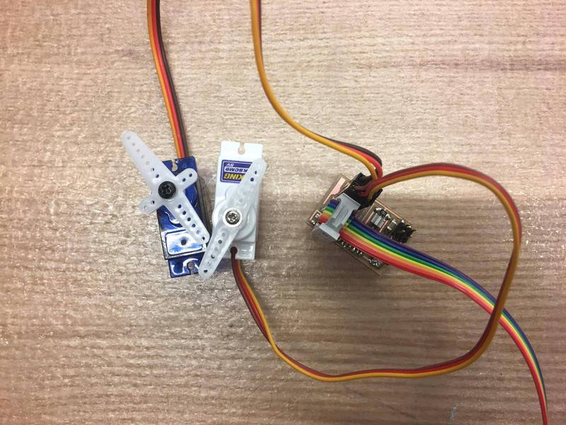
Figure 4. Connected servos to the board.
I never quite get the servo board to work. It turned out later that the schematic for the voltage regulator was in the wrong direction! Always double check the datasheet!
2. Making the RGB Board
I then made the board with two RGB for my final project. Schematic, board design, and fabrication can be found on the final presentation page. I was able to program the board and the red lit up. However, when I tried to turn on multiple colors, nothing happened. At first, I thought some of the connections were bad so I verified everything with a multimeter. Then I tried to turn on each color individually. It turned out that the green ones didn't work. After reading the email about the wrong layout for the voltage regulator, I had an epiphany and went to check the datasheet for the RGB we used. And it turned out that the footprint in eagle was wrong! So again, always double check the datasheet!