Xin Wen
Week 6: Computer-Controlled Machining
make something BIIIIIIIIIIIIIIG
1. Parametric Design
2. Machining the Standing Desk
3. Putting Everything Together!
This was a really fun week that we get to make something big. I spend most of my awake time in front of a computer while slouching in my chair, so I decided to make myself a standing desk to put on top of my desks. I made my parametric design in Fusion and extracted the 2D design through Rhino. Then I cut the pieces out on a ShopBot CNC router with help from Gavin, our section head.
Tools used: Fusion, Rhino, VCarve, ShopBot, various handheld (power) tools, e.g. power sander, saw, etc..
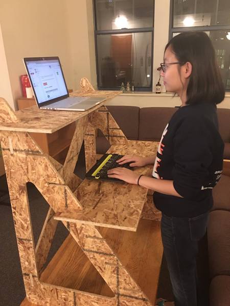
Figure 1. I am currently blogging from my standing desk!
- Basic workflow:
- make parametric design
- set up CNC and position stock
- generate and check tool path for CNC
- cut in air for sanity check
- cut out the pieces
- assemble!
1. Parametric Design
After being super indecisive and going back and forth between making the animal shelf I wanted to make in week 2 and making a standing desk, something I really need to get me out of the couch, I finally decided to make a standing desk with adjustable height that can go on top of my desks. I then measured the different heights I needed for different tables.
Figure 2. Sketch of my standing desk.
Having gotten more familiar with Fusion from week 2, I decided to make my parametric design in Fusion. For this assignment, it was especially important to make the design parametric since I didn't know what size I should make the slots for them to fit together. I followed this tutorial suggested by Shirin, our TA for getting started in designing flat-pack furniture. Couple notes:
- In Fusion, you can do copy and paste a component; then if you make changes to one of them, all of them will follow. I did this to make the left and right piece of my standing desk. If you do copy and paste new, then a new independent copy will be created.
- I made the slot size to be 0.0005'' smaller than the acutal thickness (7/16'') and added a 0.001'' clearance. It worked for some of the slots but not the others because OSB thickness varied quite a lot.
- You could (should) create dog bone corners for the joints so the mill can get in the corners but I didn't. The mill didn't really have enough space so it ended up creating the pattern like dog bone corners.
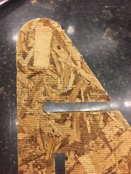
Figure 3. You can see the dog bone corner like shape in the corners.
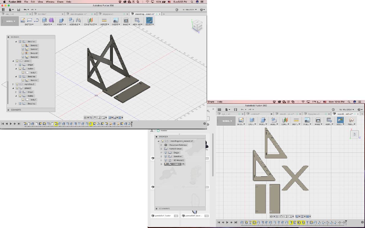
Figure 4. Left: 3D model, right: parts layed flat.
After making the 3D model, I reoriented everything to lay flat following this video. I ended up extracting the outline in Rhino with the UnrollSrf command, so it actually wasn't necessary to lay everything flat in Fusion. Here's the design file in pdf.
2. Machining the Standing Desk
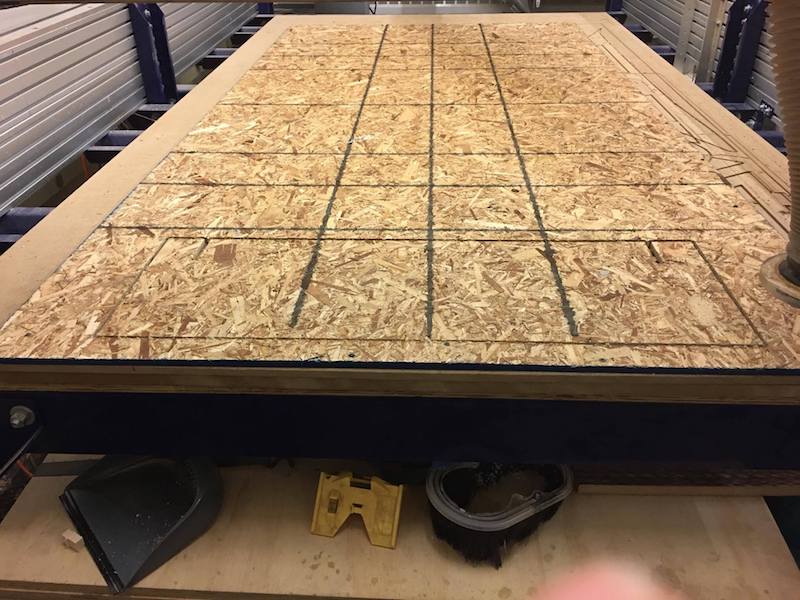
Figure 5. The sheet of 4 x8 feet OSB I was using, but it's not not meant for cutting...
The ShopBot has a sort of complicated set up process. Since it's a very powerful and huge machine, there are various safety requirements. Wearing safety goggles and putting away any danggling things (including tying up long hair) are a must. You shouldn't use the machine when you are tired or by yourself. It's also important to know how to stop the machine if anything goes wrong.
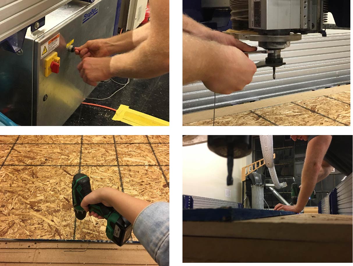
Figure 6. Top left: turning on the machine; top right: lock end mill in place; bottom left: drilling holes and screwing the stock onto the bed; bottom right: you can see part of the edge popped up a bit.
You need to make sure the end mill (for cutting) or drill bit (for drilling in place) is firmly locked in so it's not gonna become loose as you are cutting. To keep the stock in place, we screwed the osb onto the sacrifcial layer (bascially the CNC bed) along the edges. Because OSB is not super flat, we also used the shopBot to drill (0.01'' depth) between where the parts would be and put in more screws. When the machine made the drill run, it actually wasn't touching the surface where it's supposed to dent, meaning the height of the top surface varied for at least 0.01''.
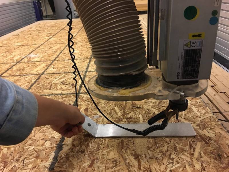
Figure 7. Calibrate z axis.
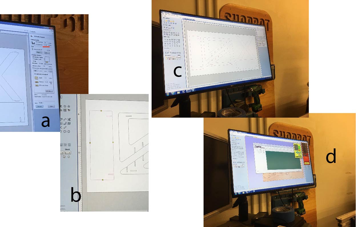
Figure 8. a) generating tool path; b) adding tabs; c) VCarve; d) the software that controls the operation of the machine has this really neat feature that once your cutting starts, you cannot move the cursor outside of the STOP button.
The shopBot I used used VCarve to generate tool path. I generated profile cut paths with 0.45'' depth (a little more than the OSB thickness to make sure it cuts all the way through) and added 3D tabs to my parts to keep them in place after being cut. I found it very useful to generate separate tool paths for each part so you can modify as you go along. After generating the tool path, you can see a simulation of how the mill will move across the surface. Before you actually start cutting your piece, you should do a test run by cutting in the air to make sure the path looks reasonable.
Simulation of the tool paths.
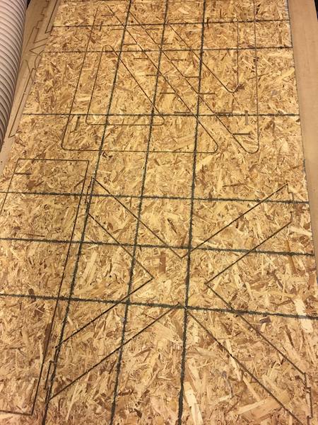
Figure 9. Finished cutting!
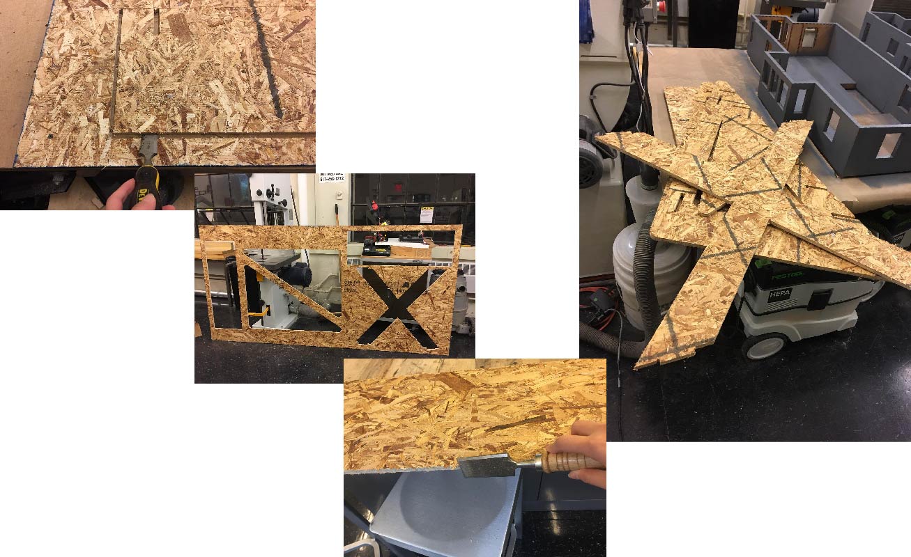
Figure 10. Breaking off tabs and breaking out pieces sticking out of the edges with a chisel. Can you spot my name ;)
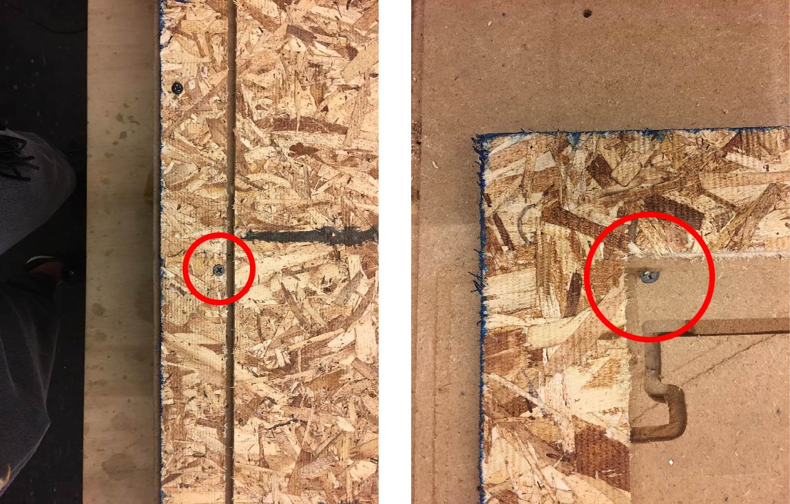
Figure 11. It's important to make sure the screws are out of the path of the mill to avoid breaking the mill. For the edge screws, I just eyeballed distance and one of them ended up being super close to the path and one of them was partially on the path so it got cut in half.
3. Putting Everything Together!
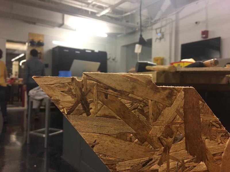
Figure 12. One of the edges was uneven so I had to manually cut out part of the joint for it to fit into the slot.
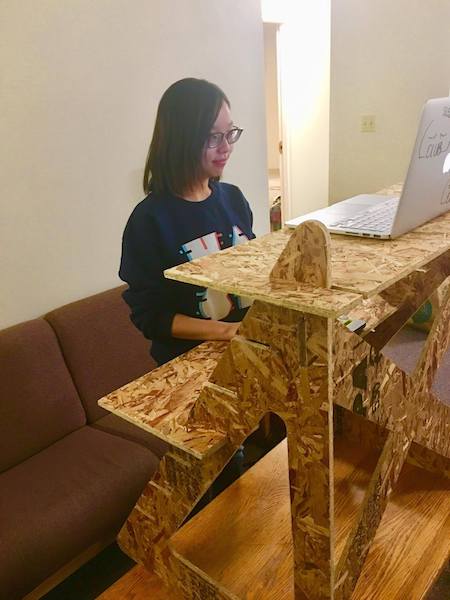
Figure 13. It's assembled! I had to use a mallet to hammer some pieces together and sand the pieces for a while, but overall the assembly went smoothly.