Xin Wen
Final Project Presentation
1. Project Motivation and Previous Work
2. Molding and Casting
3. Electronics and Embedded Programming
4. Integrating with the UI
5. Bill of Materials
6. Conclusion
1. Project Motivation and Previous Work
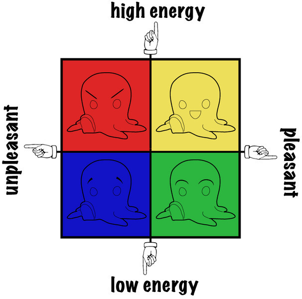
My original idea was to make a physical version of the headquarter in the movie Inside Out so that people can share their memories/emotions. Given the scope of this project, I decided to scale down and focus on visualization of emotions. This final project is largely based the Mood Meter that helps people expand their vocabulary of emotions in order to better assess how they are feeling. I wanted to make a physical version of the mood meter so people will remember more easily to check in with how they feel.
The Mood Meter categorize emotions into four quadrants along two axis, how pleasant/unpleasant and how (not) energized you feel. I used four silicone octopi to represent the four main categories and I had a UI that showed all 25 emotions assisociated with each of the four quadrants. When you click on each of the page on the UI, the corresponding page with the 25 emotions will show up and the octopis will light up briefly.
Shirin Shivaei did a physical brain map project last year where she also casted circuit in silicone and light it up by touching. I was inspired by her approach. What I did differently was that I made my own models and used RGB LEDs for the lights. I also designed my own board. Sadly, I couldn't get the touch sensing to work in time for the presentation, but I definitely want to keep working on it in the future.
2. Molding and Casting
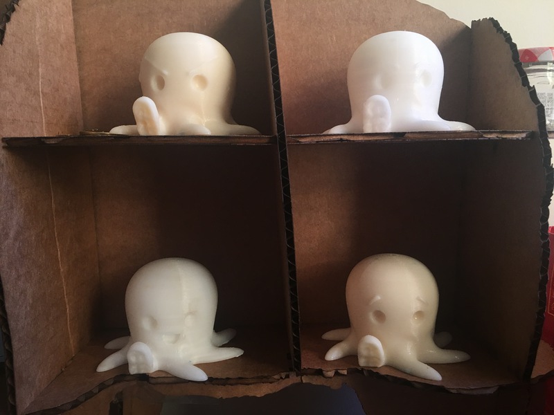
I found the octopus model on Thingiverse and modified it to give it different facial expressions (it's hard to tell their facials once they are casted in clear silicone but you can kind of see it on the 3D prints). Then I 3D printed them. The first time I 3D printed two of them on Stratesys, the density setting was too high so I used way too much material than necessary. Normally, a 3D printing job should use ~1m material. So for the last two models I printed on Zortrax with very low density.
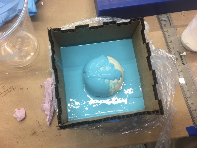
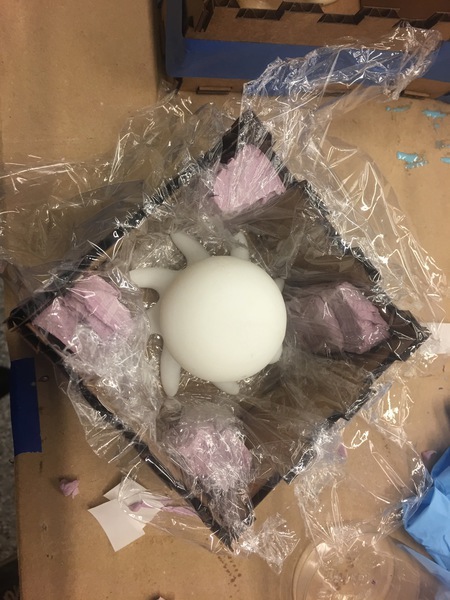
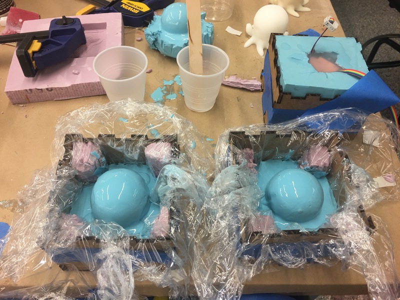
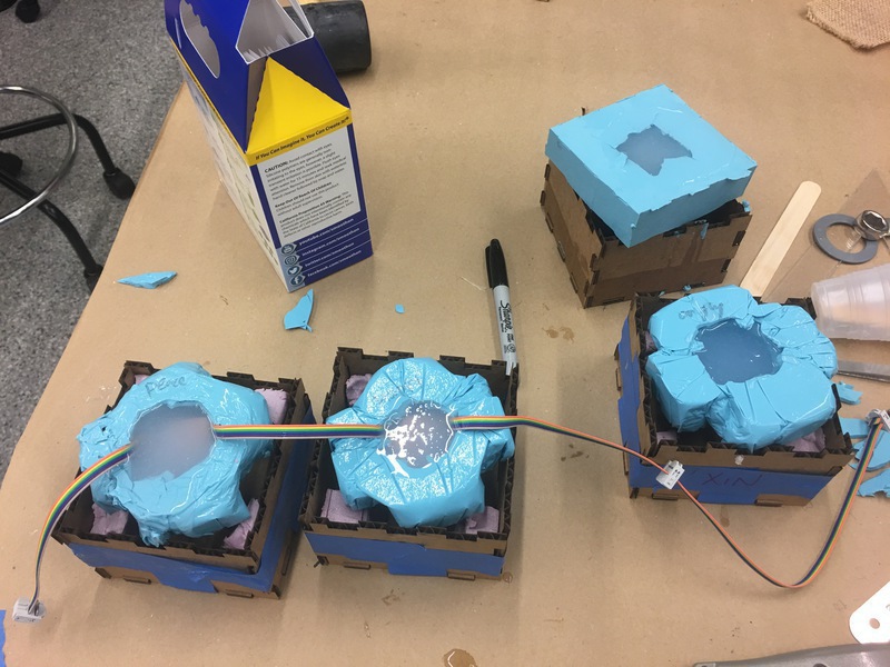
Once the models are ready, I made boxes out of lasercut carboard to cast them in oomoo to make the negative mold. At first, I just poured oomoo directly into the cardboard box and it required way too much oomoo and oomoo was also leaking out from the small openingings at the press-fit intersection. So I added foam to the corners and warped the inside with cling wrap and poured oomoo into the cling wrap for the rest of them. It used up way less material and the result was nice!
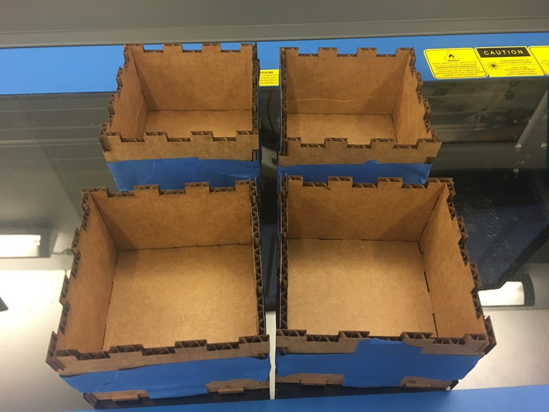
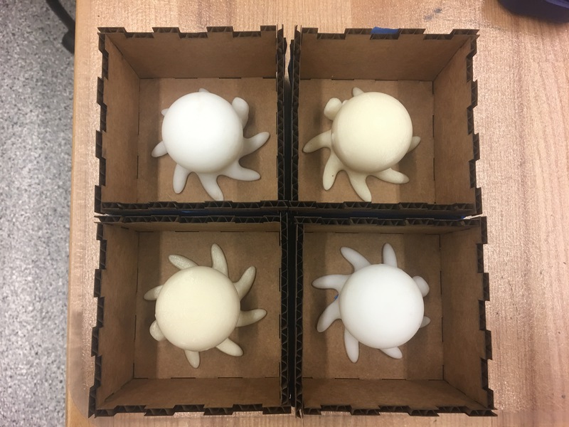
Ready to take a bath!
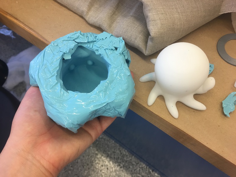
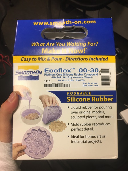
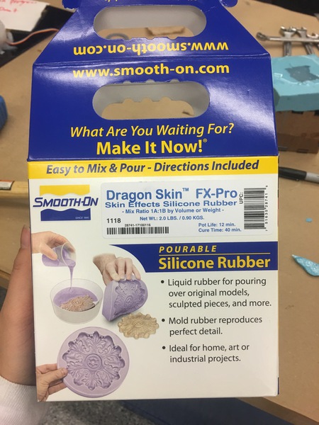
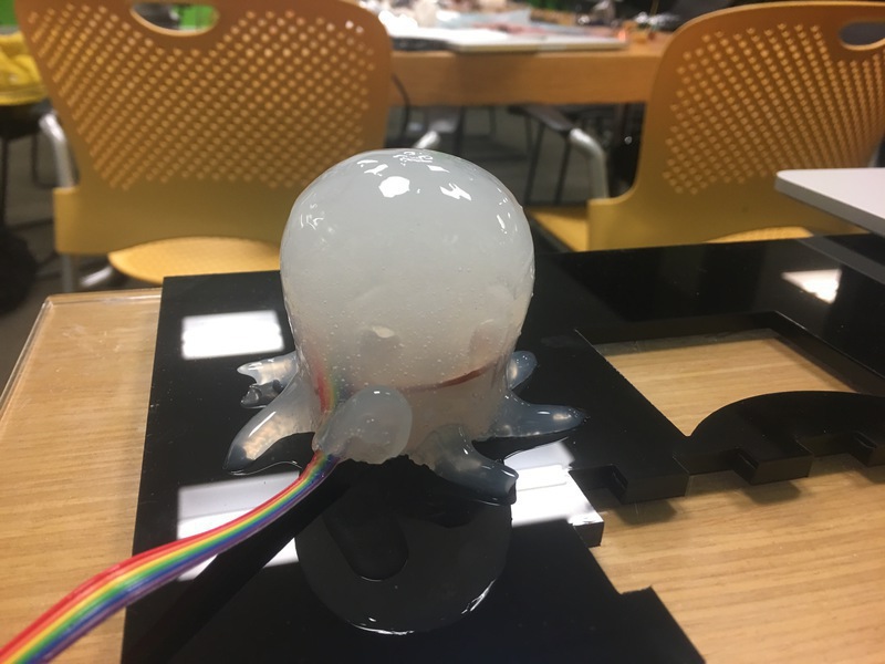
The next step was to cast the circuit in clear silicone. I first tried with EcoFlex and the surface didnt' cure properly but the RGB LEDs lit up in response to serial input! Then, I tried two other clear silicone to cast the octopi, DragonSkin, and SortaClear (they are increasing in hardness and DragonSkin has the shortest pot life). It turned out that all three of them does not cure properly on OOMOO and couple people had the problem. One way to clear the surface is to wash it with acetone. Now my octopi really resemble their natural state!
3. Electronics and Embedded Programming
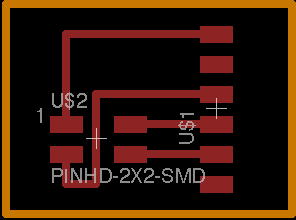
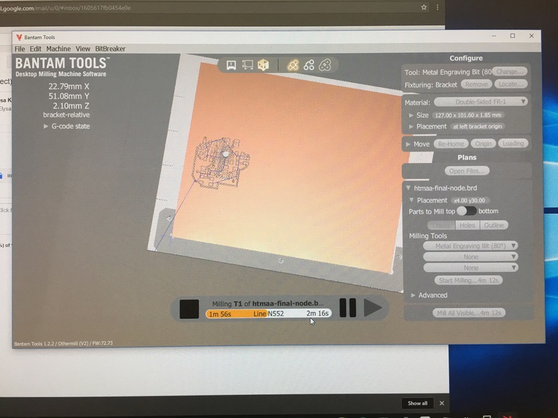
Special thanks to Allan, Mike, Ben, Casey, Max, and all the other people who helped me debugged. Initially, I desiged a board with a step response as pressure sensor, two RGB LEDs for output, and a bus connector for serial communication. The first problem I had was to route the board. I spent a really long time trying to route the board on a single layer but I couldn't get it to work. So I learned how to make vias and made the entire back as GND. I also learned how to use the Othermill and I was like why hadn't I used this all semester?
After I made the first board, I was able to succesfully program it once but not after that. It turned out that all the programmers were broken in the EDS. A good way to check if the programmer is working is to probe the clock signal on the programmer while it is talking to the device. If there's no signal, it means the programmer is broken.Max kindly let me use his programmer before I went to make a new one and after my new programmer stopped working after couple days. After endless debugging and the functioning programmer, my LEDs started to light up. However, I could never get the green LED to do anything. On the second to last day, Ben emailed out that the regulator on the example servo board had the wrong footprint so I went back to the RGB LED datasheet and of course the footprint in fab lbr was outdated so I've been connecting VCC to the green LED pin. After I fixed that, my LEDs worked properly.
Sadly, I never got the step response to work. I checked the serial output and it was indecipherable. I probed RX with an oscilascope and the timing was off so I adjusted the code. However, it was still not working. Andrew reminded me to burn my bootloader to run at 8MHz and it worked for him but not for my board. Initially, I wanted to use touch input to activate LED and bring up a certain page in my UI. Since the TXRX was not working, I tried force sensitive resistors. However, it was too late in the game so it was difficult to get the FSR to work with my already milled out board without worrying about shorting things accidentally and I didn't have enough time to design/make new boards. I was confused that the serial communication of node ID betwen the board and the computer didn't have any problem. Seems like other people also had similar problem that the board was able to send specific string messages but not variables. I am still trying to figure out how to fix it. In order to have enough time to cast the octopi, I just changed my design so that the UI talks to the board and turns on the LEDs. In the next spiral design, I would like to work on the touch input.
- C for angryOcto
- makefile for angryOcto
- C for happyOctor
- makefile for happyOcto
- C for sadOcto
- makefile for sadOcto
- C for angryOcto
- makefile for angryOcto
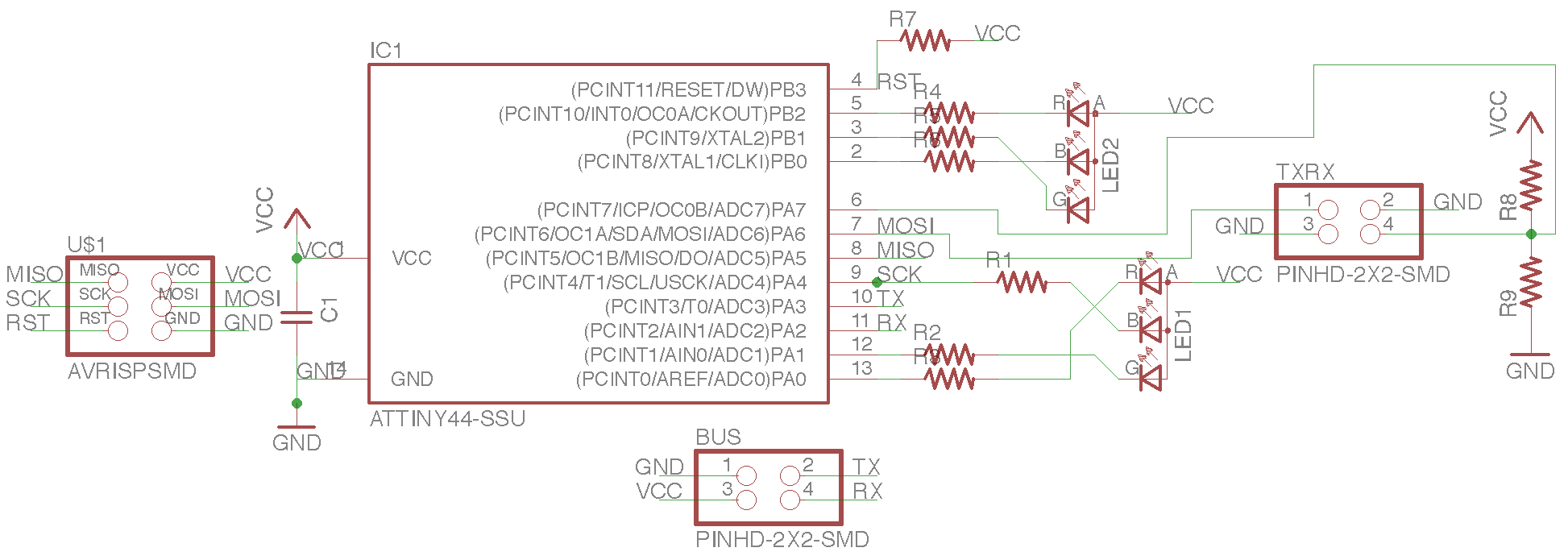
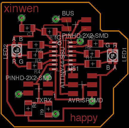
Node board.
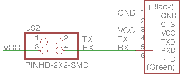
Bridge board.

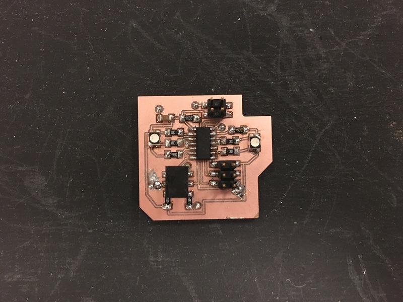
First board populated!
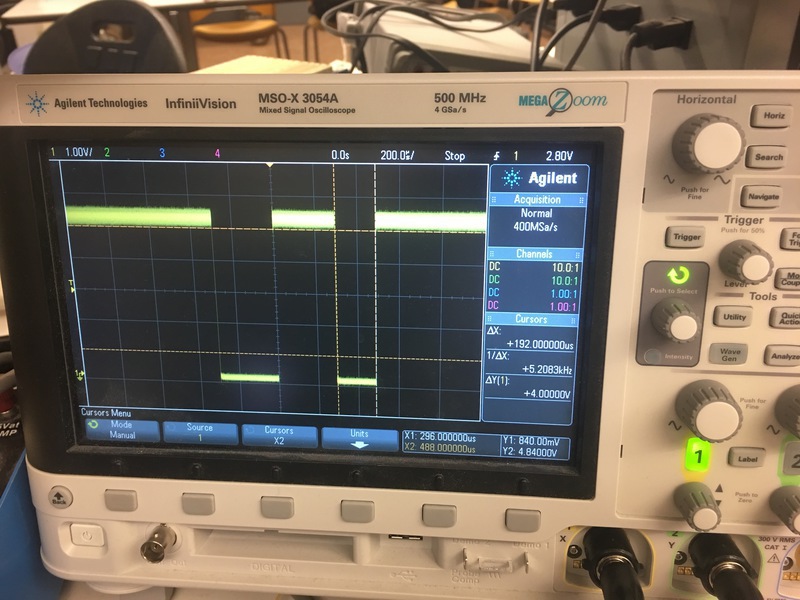
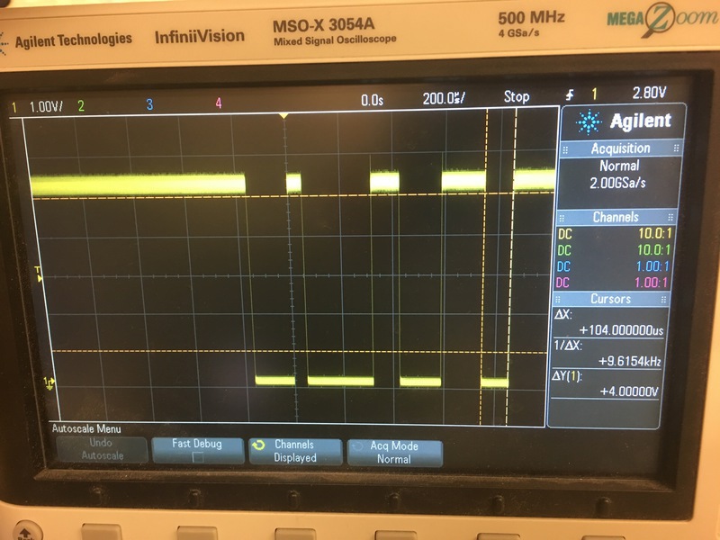
Even after the timing was correct, the serial output was still indecipherable.
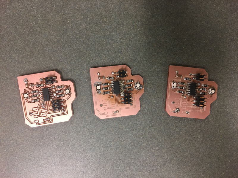
Finished making boards (the fourth one was already casted in silicone)!
Testing the FSR.
The board receives the node ID and echos its back.
4. Integrating with the UI
I wrote the UI in Processing in the interface week so during the final project week I just added the serial communication so that each page will send a unique node id to the boards and the board with the node ID will light up. Here is the final code.
Board communicating with UI.
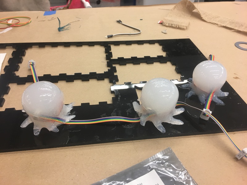
It still works in the silicone.
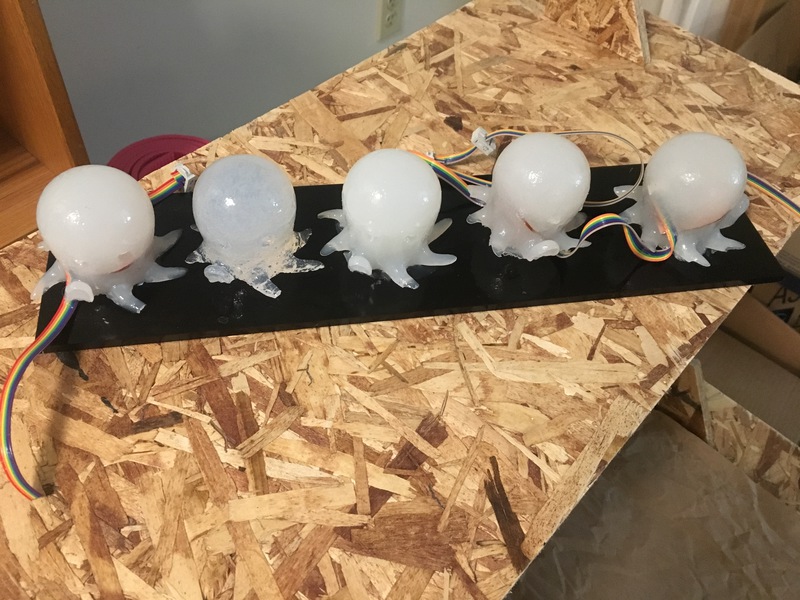
Photoshot of all the octopi (one of them is an extra)! From left to right: EcoFlex, SortaClear (it trapped a lot of bubbles), and the right three are made of DragonSkin.
5. Bill of Materials
- ~a box OOMOO: ~$25
- ~150g of EcoFlex (part A and part B combined): ~$8
- ~150gx2 of DragonSkin (part A and part B combined): ~S17
- ~150g of SortaClear (part A and part B combined): ~$10
- four 3D printed model (the ones printed on Stratesys were expensive because of the wrong density setting)
- a piece of cardboard
- ~30mmx30mm double-sided copper boards: four successful and three failed: ~$10 per board
- Electronic components for each node board: attiny44, 2x2 header, 2x3 header, 2 RGB LEDs, 9 resistors, 1 capacitor, rainbow cable
- Electronic components for the bridge board: ftdi connector, 2x2 header
6. Conclusion
Of course I wish I could have spent more time on this project but I am pretty happy with how the project turned out. The communication between the UI and the physcial modules is working so it accomplished my original goal of adding a physical dimension to the mood meter. In future iterations, I would like to get the touch sensing to work, make different light pattern based on pressure input, and make the physical modules more portable, e.g. use wifi or bluetooth module, so it really becomes a thing you carry with you to remind you to check in with yourself.