Week 4
Electronics Design
Overview
This weeks assignments were to redraw the echo hello-world circuit board and to add an LED and a button which can turn it on and off. This is a number of steps as follows:
1. Redraw the echo hello-world board in the schematic mode in the program eagle and add a button and LED with a resistor.
2. Set the design rules to give enough clearances and thicknesses for the traces for the milling to go well.
3. Lay out the board in the board mode of Eagle.
4. Check to ensure you havent forgotten anything and that it is following the rules you set by running the Design Check.
5. Draw polygon around the board, and put this on a different layer. This will be the outline which you will cut the board out with.
6. Export the two layers separately to png. Ensure they are the correct sizes and open in mods.
7. Mill the boards using a CNC router, solder the components.
8. Once you have successfully milled the board, you need to use the Programmer from the second week. You need to send power seperately to each board, and make a cable to connect the two. Plug in the programmer to your computer and and the new board to the program and upload the program to the new board.
Having no experience doing these things previously, this week was particularly difficult, and for future reference, I would recommend adding additional time this week for figuring this week out if you are starting as a beginner. Also it is especially important to get more help this week from TAs and other students in order for this not to take way to long. Below I have listed as best I can my own experience from solving a number of problems which arose during this week, which hopefully will be helpful to anyone in the future, but I would recommend comparing with other people in case there are changes in the computer or fabrication setup.
0: Harvard Equipment Tutorial:
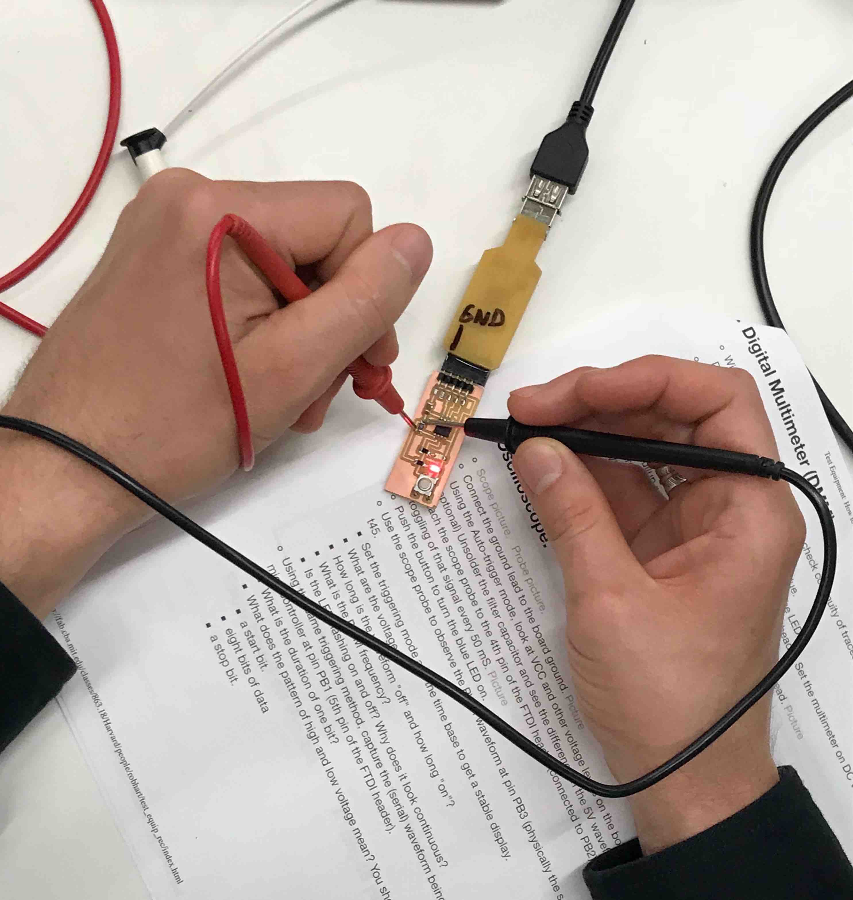
The first thing we did this week was attend a tutorial at Harvard. While there we learned how to use Electrical Circuit Testers/ Multimeters and oscilloscopes. While I left with some questions, this was helpful in getting a sense of what each component of the board was doing in relation to the others.
Board Design
Step 1
Redraw the echo hello-world board in the schematic mode in the program eagle and add a button and LED with a resistor.
Eagle: The first step towards completing this weeks assignment is to install Eagle. You can find this on the Autodesk website, and gain access to a free educational license. Eagle is a tool specifically used for electronic circuit design, which allows you to design both schematics and the milled circuit board layout.
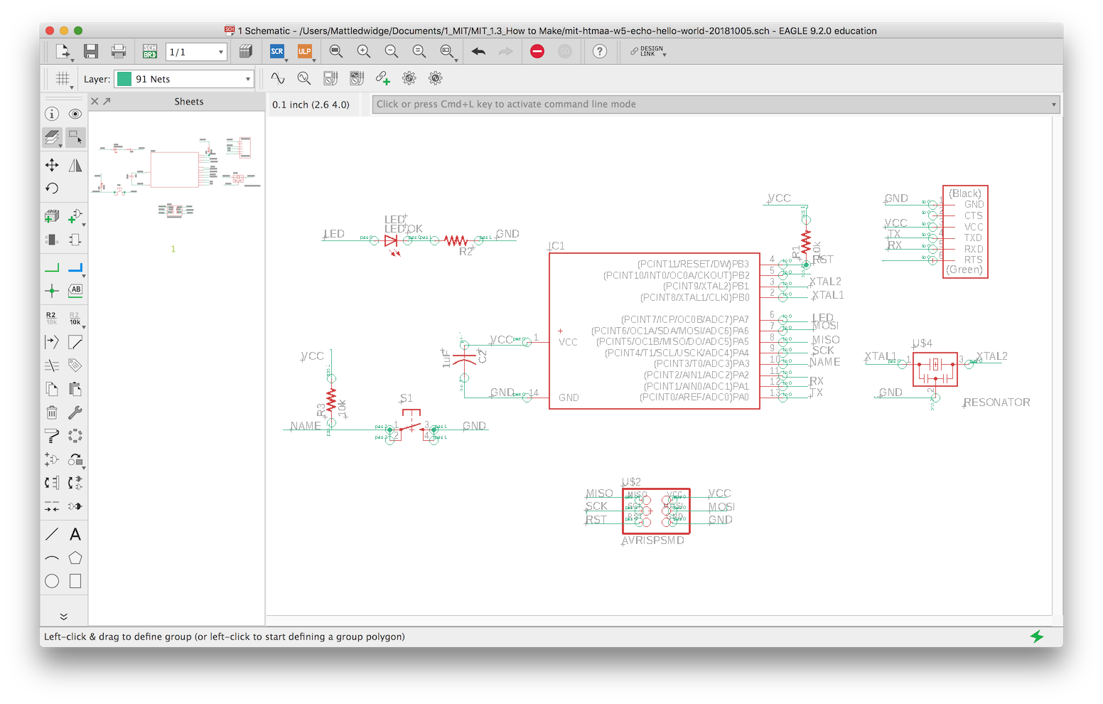
Schematic Design: The schematic is a conceptual design of your board. It shows you the way in which each components should be linked conceptually, but doesnt draw the links directly. In Eagle (for mac at least) the toggle between Schematic Mode and Board mode is the fourth button from the left in the top left. (pictured on the right).
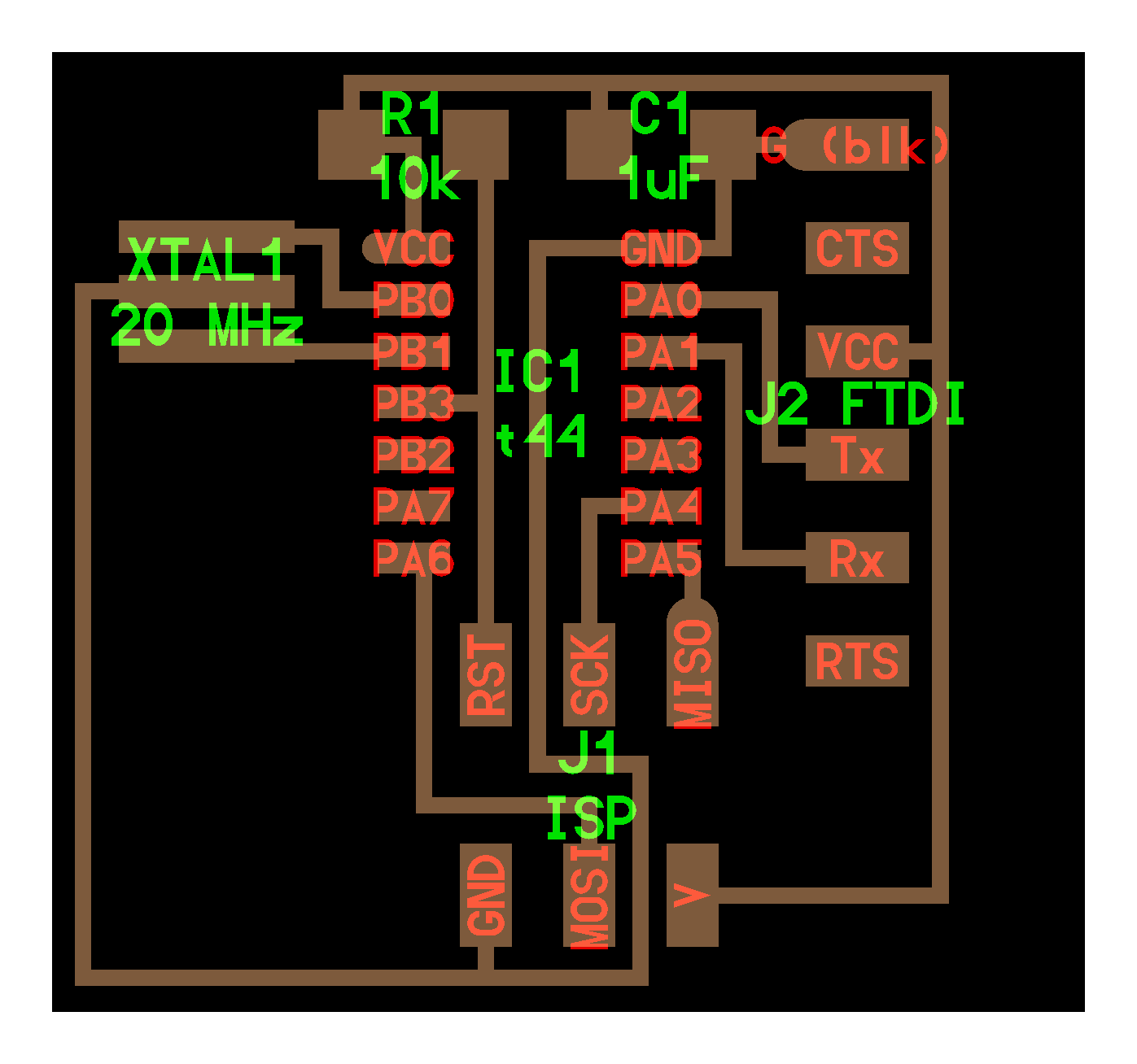
Import Fab Library: Once you have installed Eagle, you need to install the Fab library from the How to Make website. Once you have this, you will be able to add the different components we have access to in the lab, which you need to design the basic board designed by Niel. When you are looking for parts it becomes somewhat daunting, as there are thousands of different parts available. Just make sure to only use the ones from the Fab Library. What you need to do this week is translate the image to the right from Niel and figure out how to add a button and LED with a Resistor. But first the parts from the basic board are:
XTAL1 20 MHz is a resonator, which is listed under RESONATOR R1 10k is a resistor, which is listed under RESISTOR1206 C1 1uF is a capictor, which is listed under CAP1206. IC1 t44 is a microchip, which is listed under ATTINY44. J1 ISP is a microcontroller, which is listed under AVRISPSMD. J2 FTDI is a microcontroller, which is listed under FTDI-SMD-HEADER.
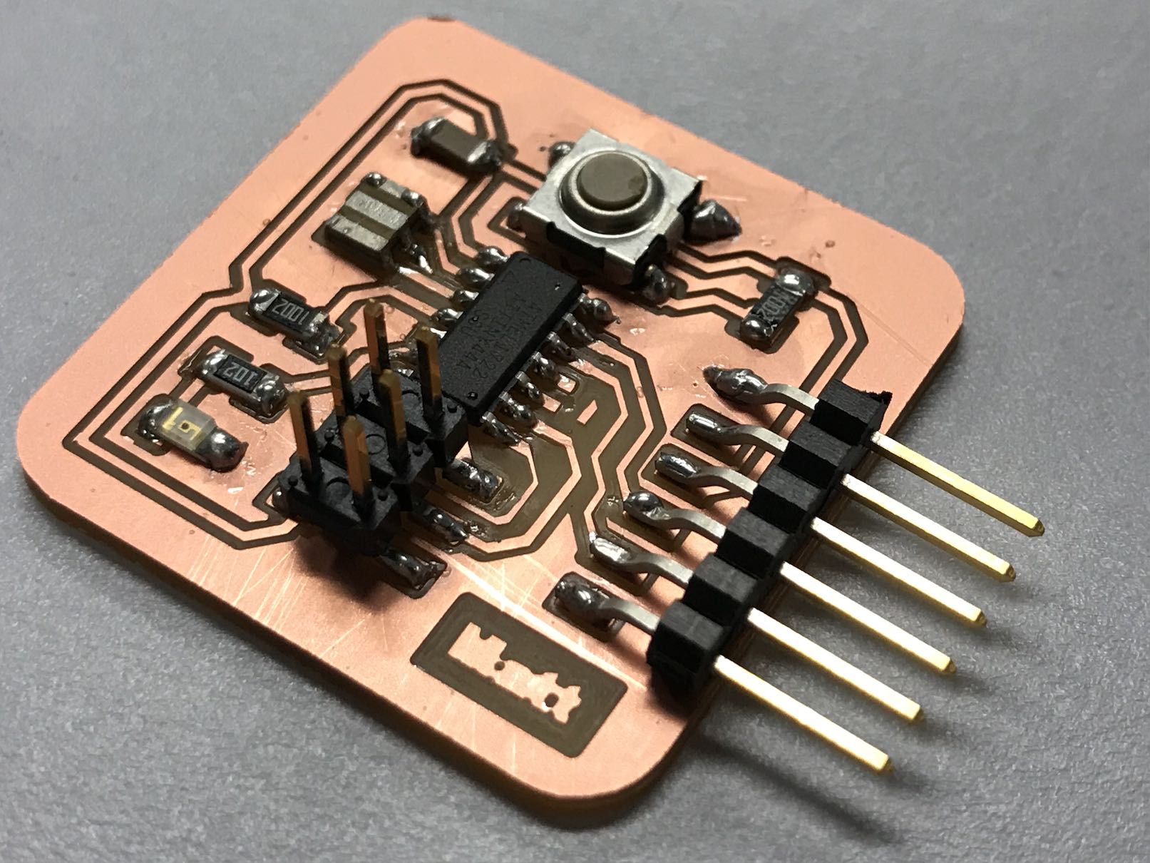
The parts you need to add: A Switch/Button: Search for a 6mm switch an LED: We used a Red LED a Resistor: there was some confusion if this should be 499 Ohms or 1000 Ohms, but we decided to use 1000Ohms (marked 1K).
Schematize: Once you have all these down you need to organize them into a a schematic design. This shows how the parts functionally are working together. You can break them off into functional sections (ie. an LED and a resistor do not need to be directly connected to the ATTINY45, but you put a label which points the what it is connected to ). You label these and can draw the lines which. The parts appear in red and the lines appear in green. Image is shown to the right. Another thing to know is that you move parts around by clicking and dragging on a tiny cross roughly near the center of the object, these as well as the titles can get lost, so try to keep them tougher.
Step 2
Set the design rules to give enough clearances and thicknesses for the traces for the milling to go well.
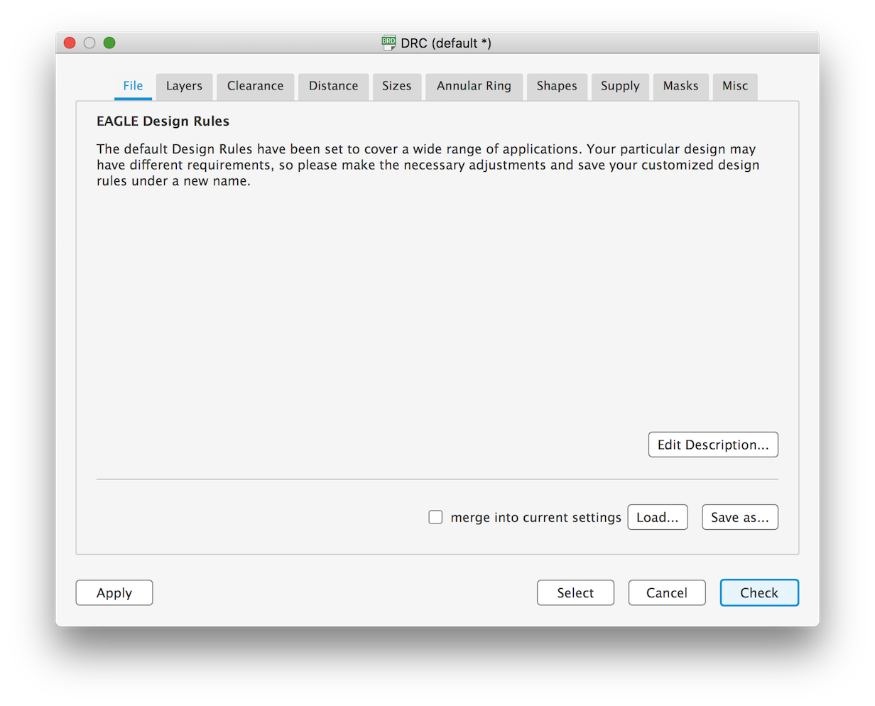
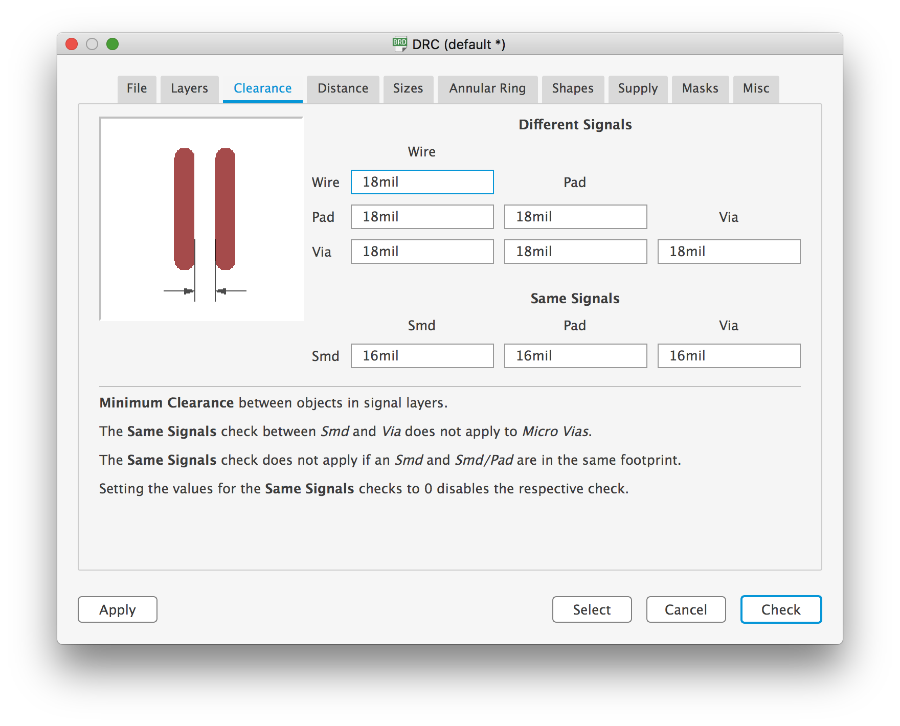
Design Rules: Before you start drawing you should set the Design Rules. The way to do this is enter in the command line (which looks like a search bar at the top) the words: DRC. the DRC are the rules you follow when drawing the board. It is useful to change the defaults to make it easier when you are soldering. Under CLEARANCE we changed all of theses this to 18 Mil to accommodate the largest 16 Mil end mill ( the 1/32 one). What this means is the setting for how much clearance there will be around each trace. Also set the Mil traces to 16 Mil just be sure they are big enough, so that they aren’t overly fragile when milling and easier to solder.
Step 3
Lay out the board in the ‘board’ mode of Eagle.
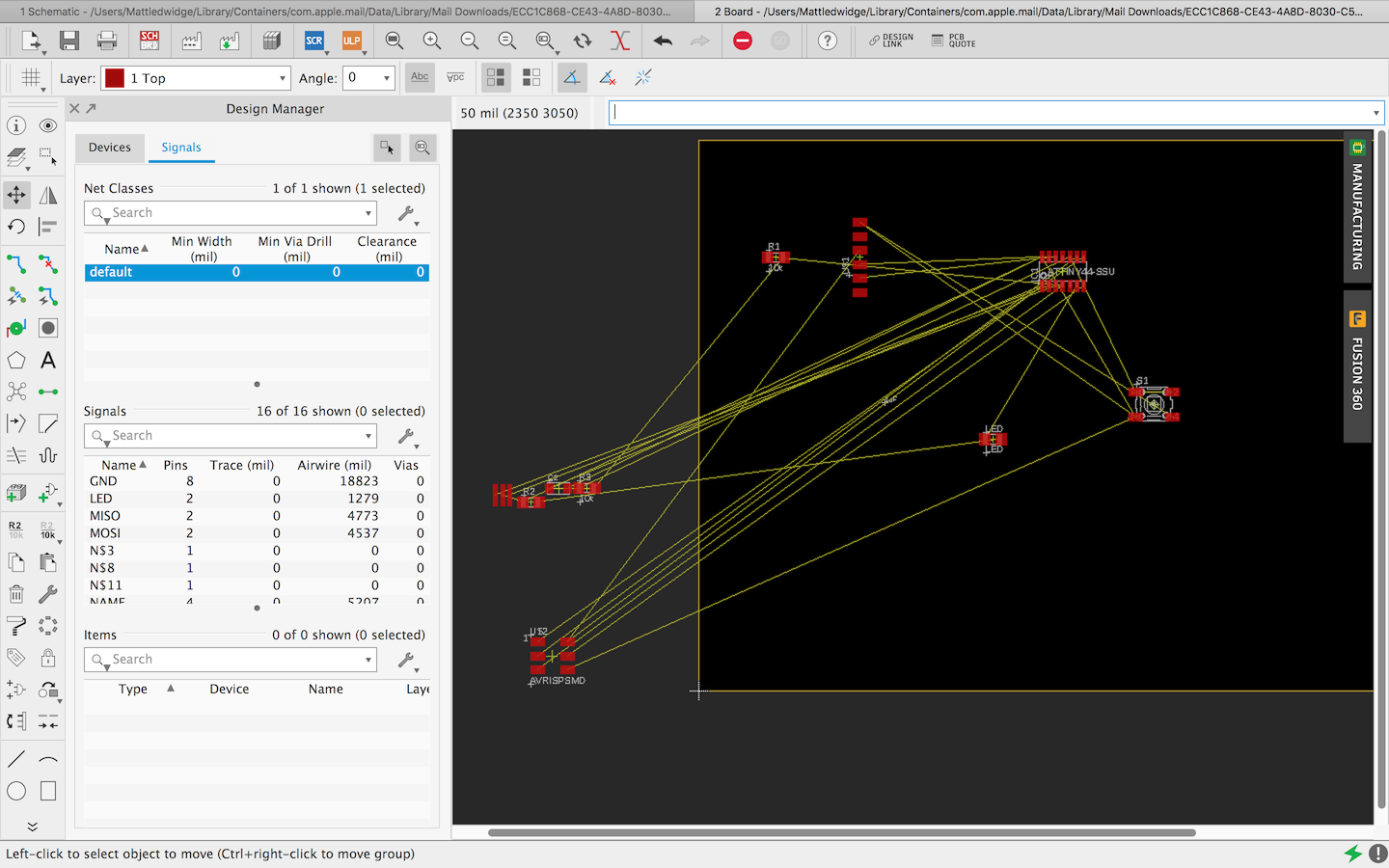
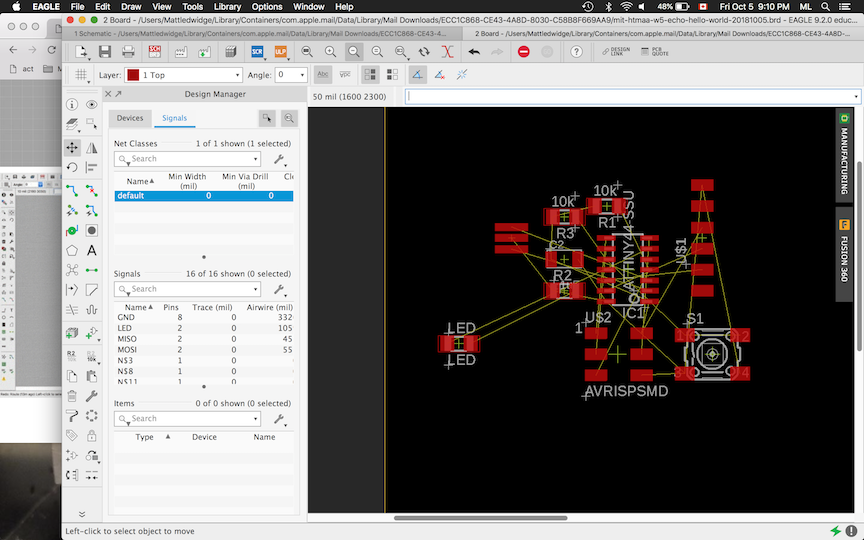
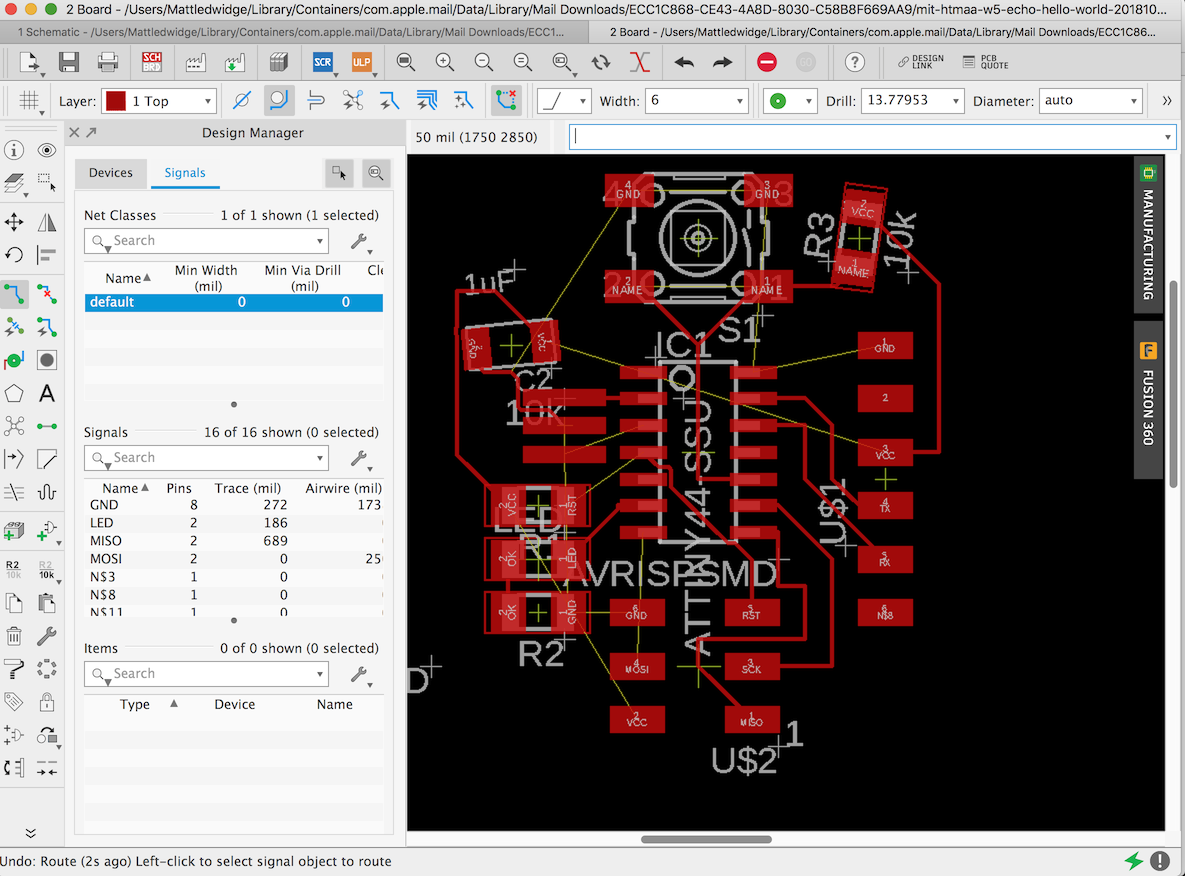
Board Mode: Once you are finished with the schematic design, switch to board mode by clicking in the top left as described above. That will take you to an interface pictured on the right. It will show you a black frame which is the board and a dark grey background around it. You pieces will automatically be placed just outside the board and appear in white, with the traces that are required for each piece shown as red rectangles. Between each component it will show you the conceptual connections required in yellow.
The first step you need to do is move these components into the center by dragging on the cross. There are two ways of operating in Eagle. You can either enter into the command line instructions like move or rotate, or you an use the tools in the toolbox on the left.
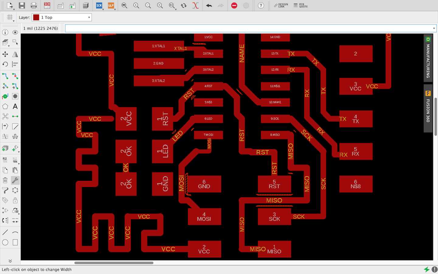
Either way move them into the middle of the black box with a yellow outline and what you will see is a big mess of yellow connecting lines. What follows is basically a puzzle, what you need to do is find a way to make physical traces that match the yellow conceptual lines that are coming from the schematic design. In order to draw a trace the command will be ROUTE, or you can press the icon in the top left of the third partition of the left toolbar ( it looks like a blue line connecting two red dots. If you need to delete traces the command will be DELINK, just to the right ( it looks like a red X across the blue line).
Grouping Functions: What you will find when doing this is that you can generally group certain functions together, and we found it is generally helpful to look at the way people have placed things in the past, though there are a number of ways to solve the problem.
Impossibility: You will likely encounter situations where it will be impossible to make traces and you have to move components or redraw traces for it to become possible.
Rotating: It will be easier to do this if you rotate the components in various ways to reposition the yellow lines, the best way to do this is: CNTRL + Right Click.
How to Connect: If you have spatially separated components with the same name, like GND, they all connect. It is good to do the GND (Ground) last.
Space it Out: If you are doing this for the first time, I recommend not making the parts too close as this will make it a bit harder when milling and soldering.
Grid Size: It will be useful to have more fine tuned control over your component placement and for drawing your traces. In order to achieve this enter GRID into the command line. Set SIZE to 1 in order to move things in smaller intervals.
Trace Drawing: You can draw the traces how you want, but it will default to 45 degrees and 90 degrees, which will limit the risk of milling issues. You should also know that you can go under many components, such as the button or ATTiny to form connections.
Step 4
Check to ensure you havent forgotten anything and that it is following the rules you set by running the Design Check.
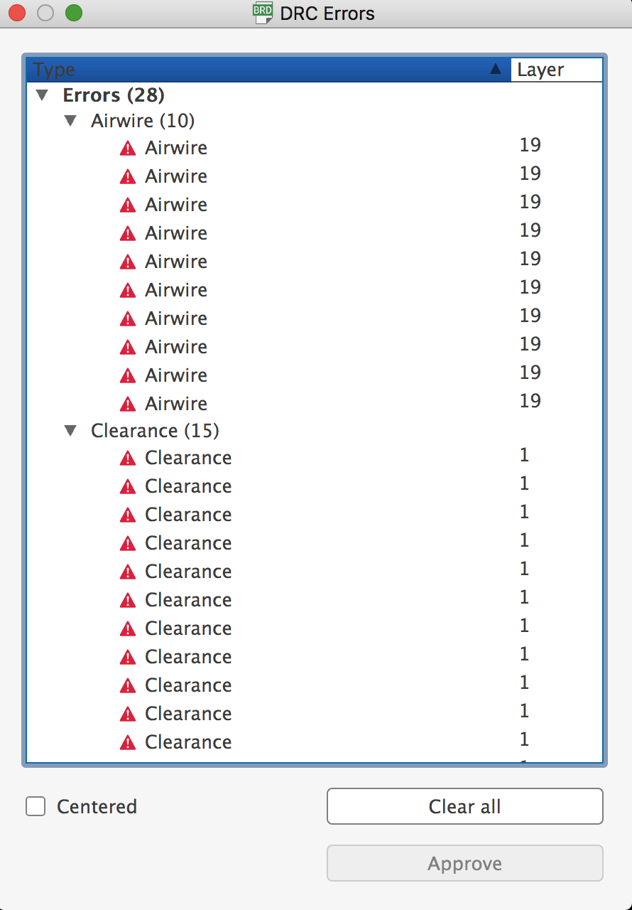
Design Check: At the end of the process, you need to run DRC which opens the design rules interface. Click check. You hopefully will not get any errors, but if you do they will like say things like AIRWIRE, which indicates that you have missing connections, or CLEARANCE which indicates insufficient clearance between two traces or a trace and a component. If you click on any issues it will show you where they are.
Step 5
Draw polygon around the board, and put this on a different layer. This will be the outline which you will cut the board out with.Export the two layers separately to png. Ensure they are the correct sizes and open in mods.
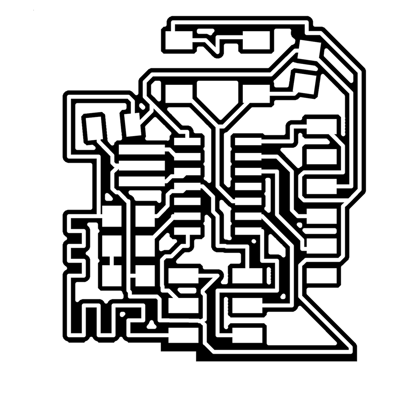
Draw Outline: Once you have successfully connected all the different components without any DRC issues, you are ready to export the board. You need to draw the outline which will be cut out by entering POLYGON, to draw the shape. While drawing, you can hold down CTRL+Click, to change the generated shape, if you are trying to create rounded or beveled edges.
Exporting: To export the different required files, you need to make them each independently invisible. To do this enter the command DISP NONE, Then, to see just the polygon outline enter the command DISP DIM. Click File>Export>Image and export a 1000dpi png file, and select MONOCHROME. To export the trace layer, enter DISP NONE, then DISP TOP and do the same to export another .png file for just the traces.
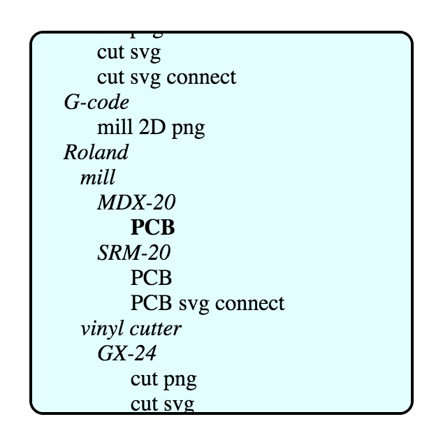
Open in Mods: Go to Mods.cba.mit.edu, Select programs>open server program>Roland>mill>MDX-20>PCB ( Or select whichever machine you are using). In the first module in the top left, click select png file and insert first you mill trace file. you need to do this one first, because once you do the outline layer it will move around.
Issues You May Experience:
Groundplane: We followed the instructions of one of the TAs suggesting using a ground plane. This is when you fill in the outside of the board with copper and use this as the GND, rather than connecting the grounds independently. This makes soldering more difficult and is not recommended. If you do want to do this, do not connect the GND pads, and instead once, use the RATSNEST command and set it to GND.
MAC Retina Display Issue: When exporting from Eagle, if you are using a Mac with the Retina Display, before sending to mill and opening in the mods, open the file. You will find the pixel dimensions are two times larger than it should be. You can either make it 50% smaller manually (in photoshop or preview) or make the dpi in the first mods module to 2000dpi to compensate there.
Step 6
Mill the boards using a CNC router, solder the components.
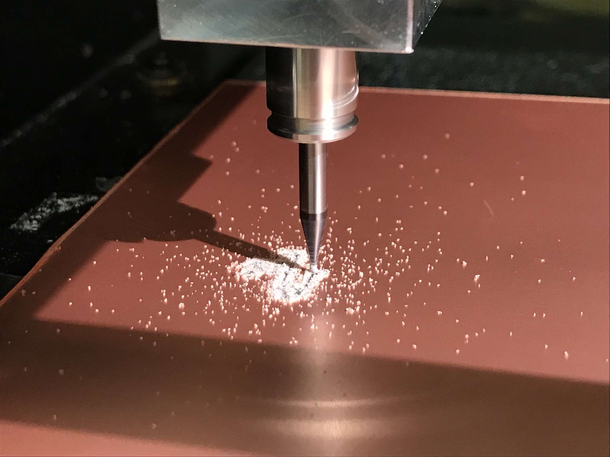
This should be identical to the process you learned in the earlier PCB Fabrication week. When you are doing the mill traces, select mill traces, calculate, set your origin, ensure the status is set to open, the mill is in the correct location and send the file.
Issues You May Experience:
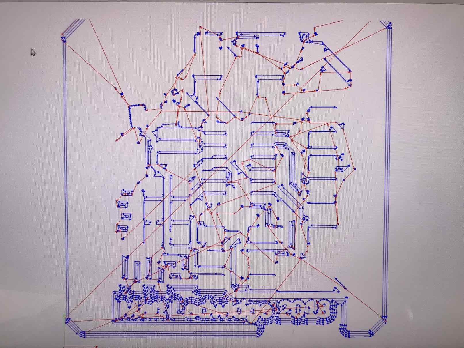
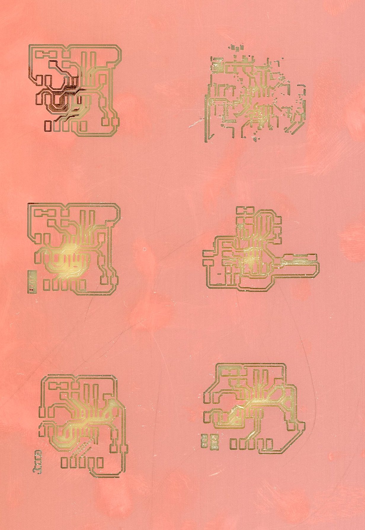
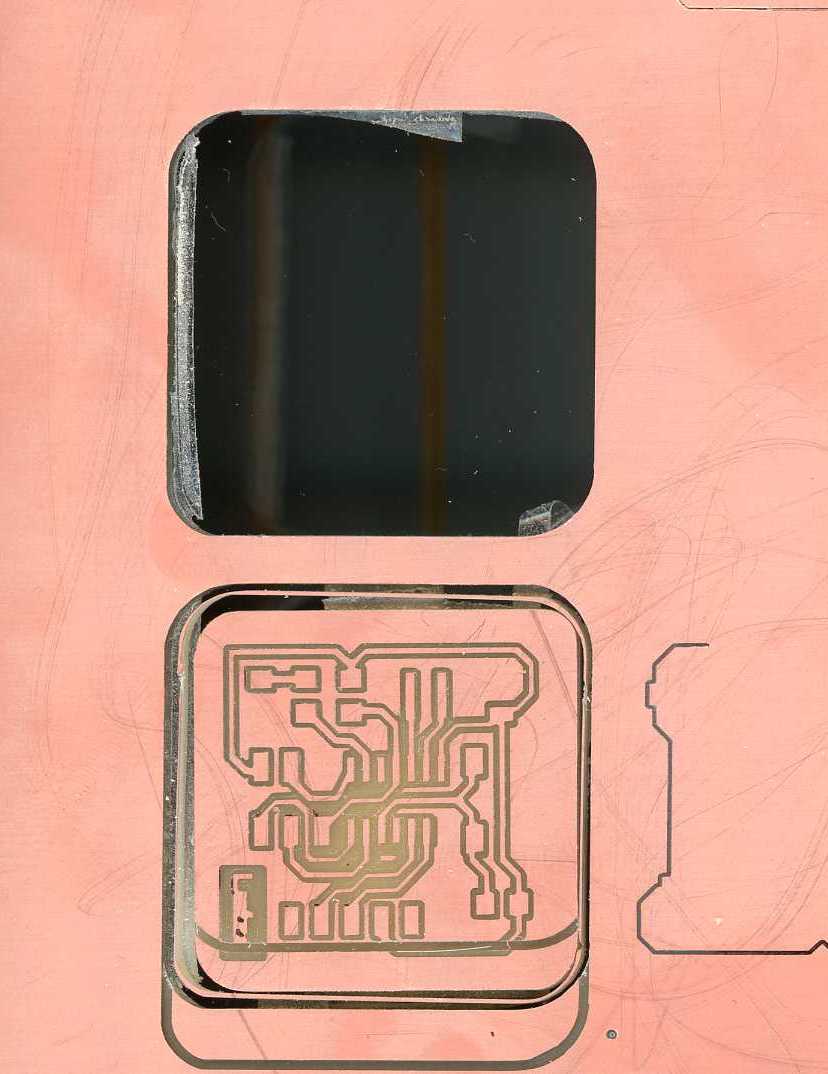
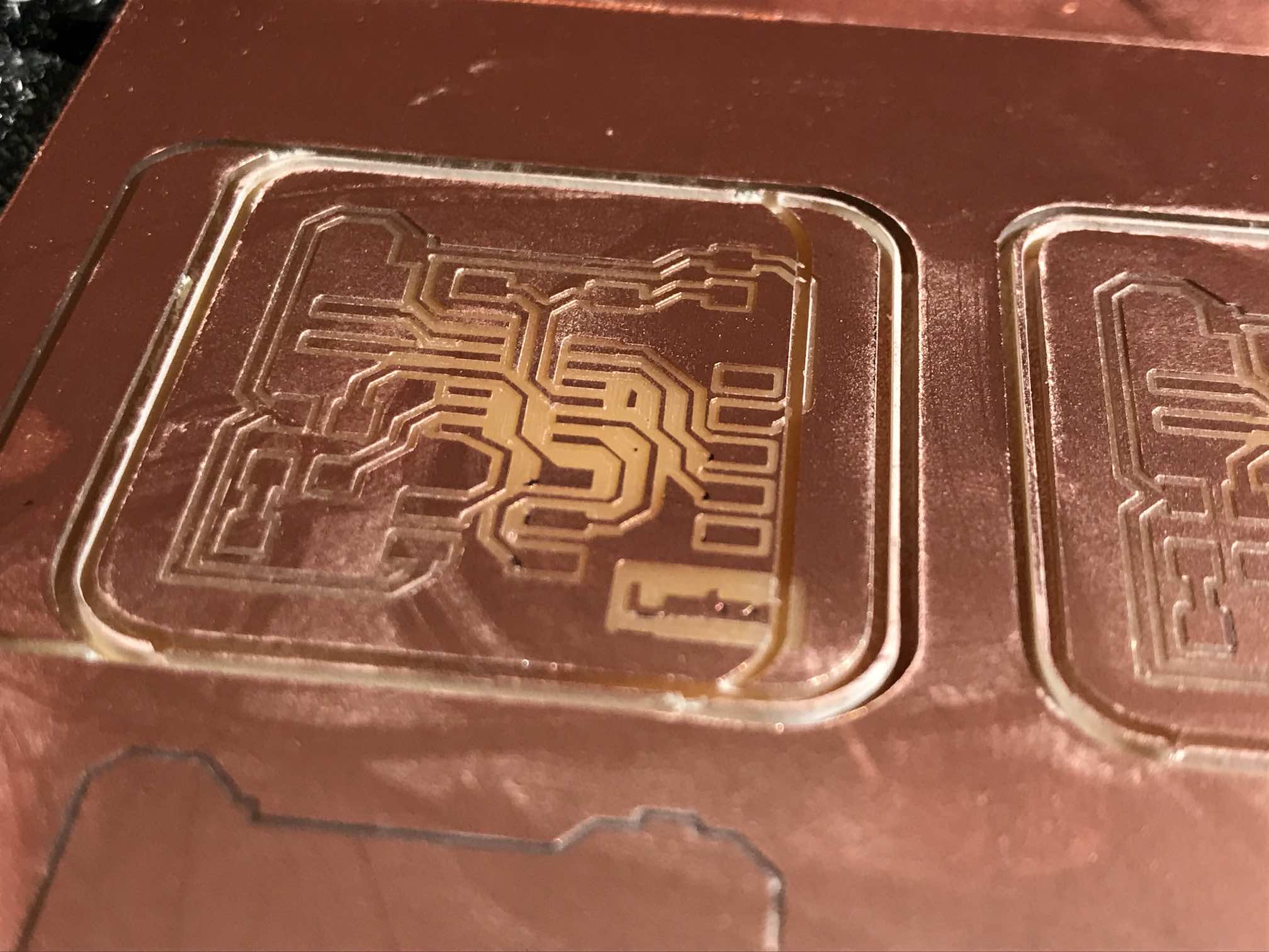
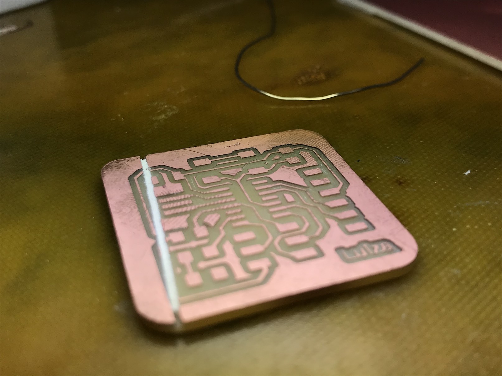
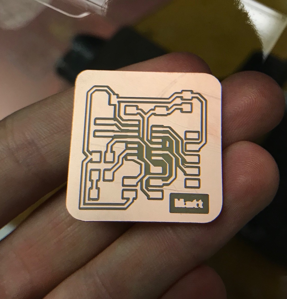
Messed up Toolpath: I converted everything to a png and loaded into mods, but when it converted to tool path everything seemed to be coming out strange. I believe what was happening here was that I had set my DRC rule values too low, which meant the mod was reading my file inconsistently. We tried milling it anyway, this is pictured on the right amongst a field of failed boards for many different reasons.To solve this, make sure to add extra clearances and make the traces thick so the mod server doesn’t ignore them as sometimes it doesnt notice tight corners and they dont get milled as you can also see on some of the boards.
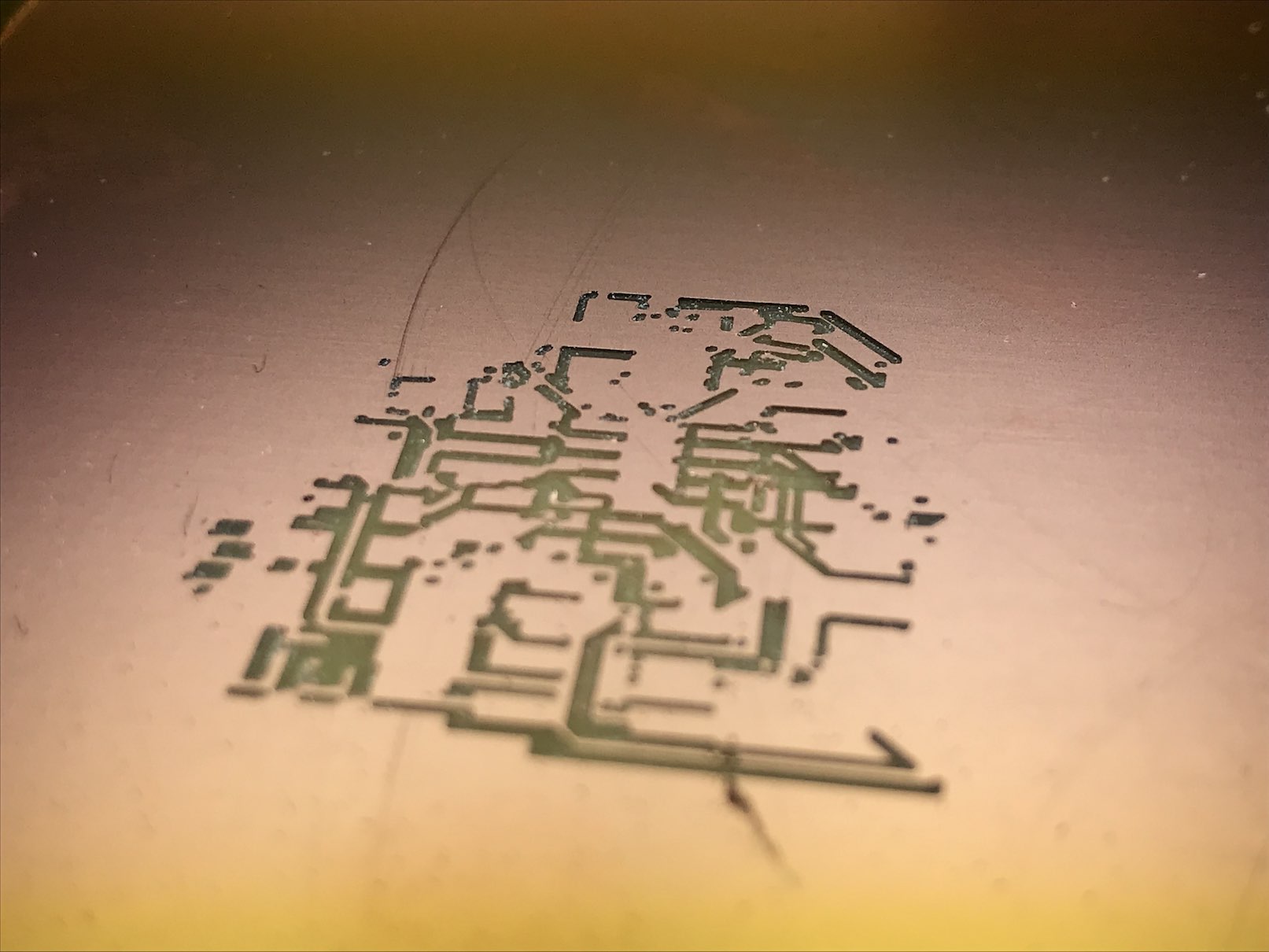
Computer server communication: A number of issues emerged from the communication between the machine and the mods program. Here is how you avoid that: When you cancel for some reason on the mods, wait for it to stop making noises and spinning before you do anything. Do not just shut off the power.This can mess up its communication to the sever, but can sometimes take up to a minute for it to fully cancel depending on where it is in the cut. flashing lights; when you stopped the machine and you don’t want it to start cutting again after you start it, if the lights are flashing it means there might be something in the queue. To cancel the queue press the up and down buttons on the machine at the same time and the lights should turn solid. If the mods program is not responding normally or returning to Zero, you need to close the program and restart the connecting to the server which you can see on the desktop. Lastly, make sure that the topmost right module called WebSocket serial indicates an open serial server status. If you do not make sure all these things are correct you can get ghosts which might cut straight through your board (pictured right).
Safety: Dont hold the end mill while you are raising or lowering it, always tighten it with the socket wrench when lowering and raising it before holding it while you adjust it to loosen it. I am told you are apparently also supposed to wear safety glasses to avoid blindness.
Uneven Board: Always check that the sacrificial layer is not too dirty. Often times problems with the board being uneven and cutting incorrectly, or with the end mill breaking is often because the sacrificial layer or copper is uneven. Be careful to lay the tape down smoothly, and to clean the machine surface when replacing the sacrificial layer.
Board Outline: When you make a cutting outline fore Mods, white is high and dark is low. The board will offset into the external direction from the interior. What this means is that when cutting out your board you need to invert the border file for mods when you are milling. This will cut on the inside of the line instead of on the outline.
Step 7
Once you have successfully milled the board, you need to use the Programmer from the second week. You need to send power seperately to each board, and make a cable to connect the two. Plug in the programmer to your computer and and the new board to the program and upload the program to the new board.
Programming:
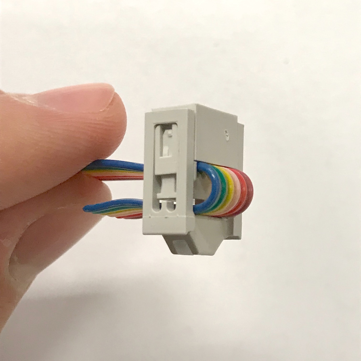
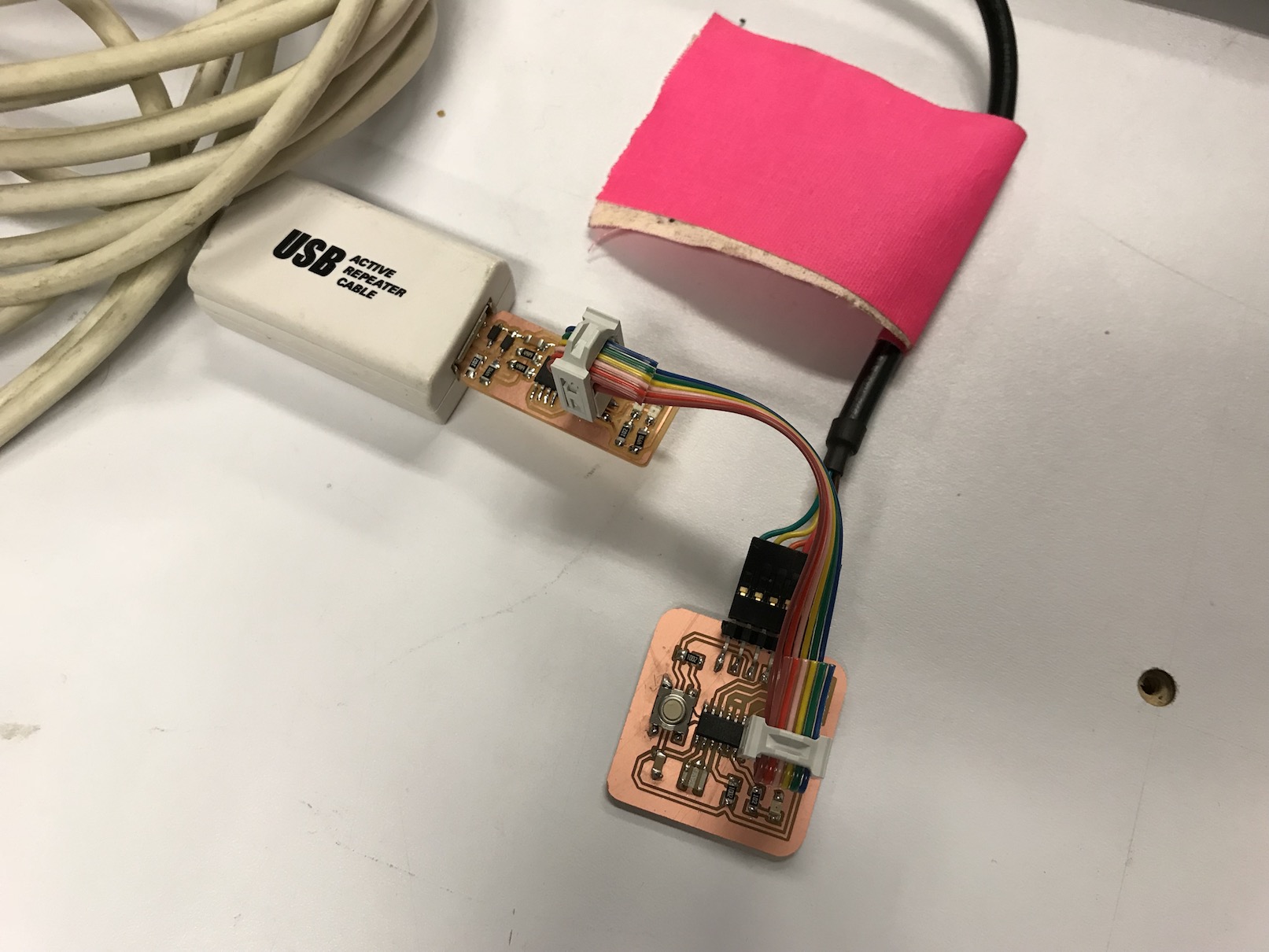
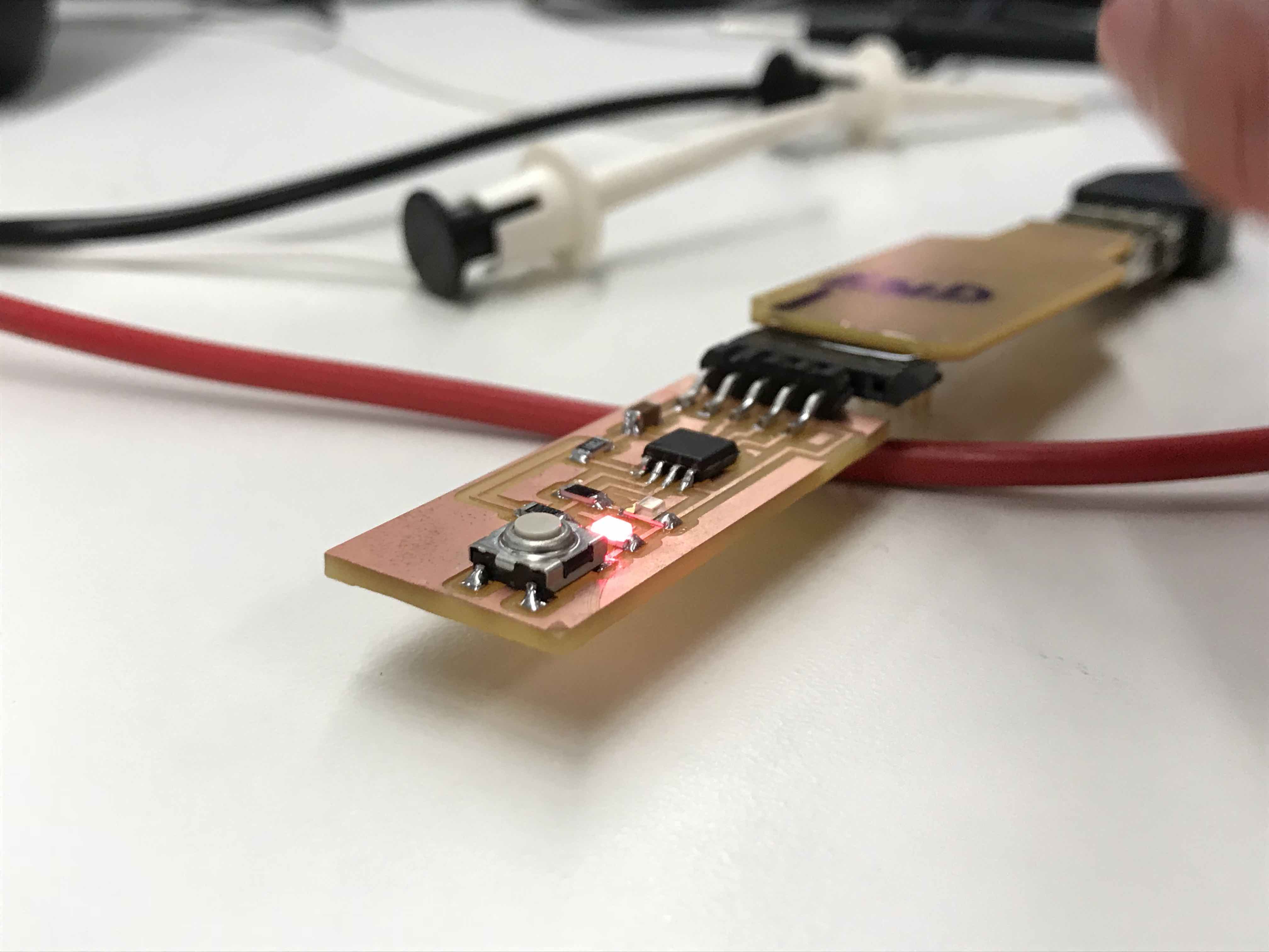
Congrats on making it this far! I am definitely not the right person to look at for this part, because still don’t full understand, but can give a loose outline here and some things you should look out for. The general idea is that what we designed a few weeks ago is a programmer which is what we will use to program the board. What this means is that each board will need its own USB cable plugged into a power source (the computer), and a special 6 pin cable will run between the two. If you have not yet gotten the programmer from the earlier week working, you will first need to do that. Once that is working, you need to make a cable to connect the two boards (pictured to the right – these supplies are in the lab, but cant remember all the names). Many people in our course were not able to successfully, so if it didn’t happen this week, dont worry too much!
Issues Encountered and how to avoid:
(Partly based on instructions from Ben Yuan):
Miling: Board is milled correctly (traces are properly isolated).
Shorts: No shorts between power and/or data lines.
Open Circuits: No open circuits between t44 pins and corresponding connector pins.
Solder Joints: Solder joints are in good condition. Make sure the joints are smooth and shiny, not grainy and blobby.
Accidental Solder: No unintended solder bridges between adjacent pins / traces.
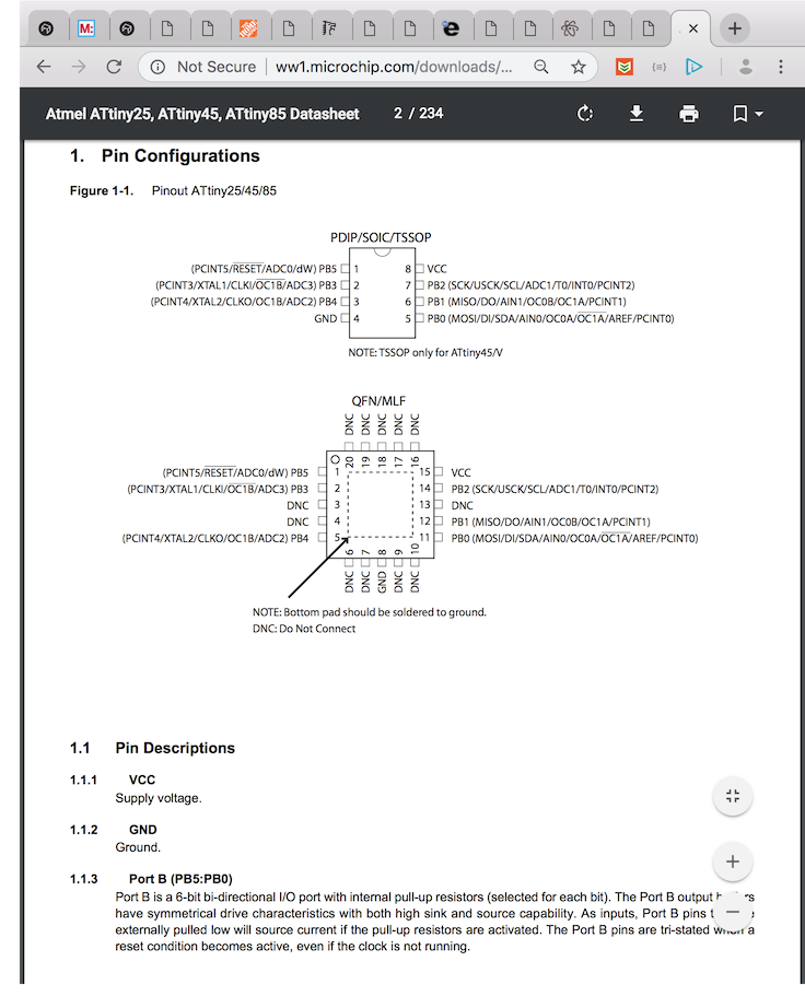
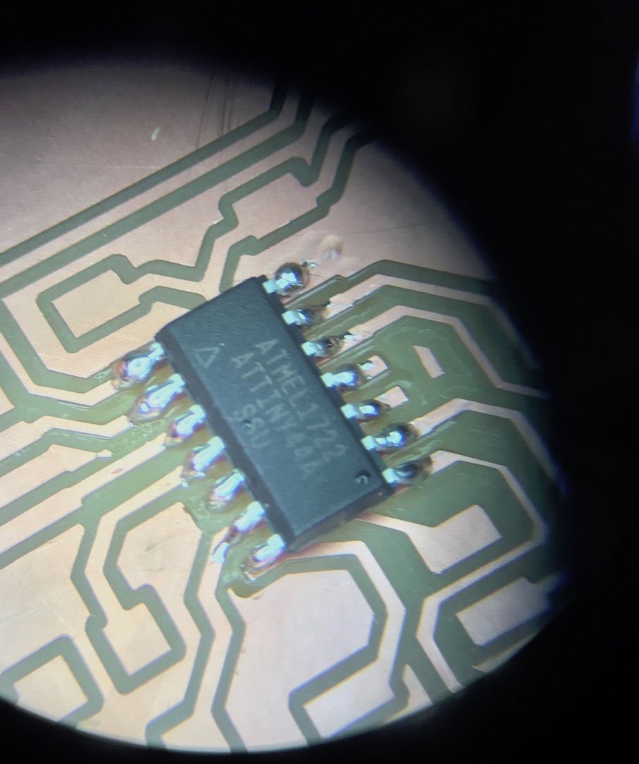
Component Orientation: t44 is oriented correctly on board (check pin 1 indicator). Make sure you figure out the orientation of all the components are oriented completely, check the data sheets per components and compare with your design.
Clock: Required clock source is present on board (depending on how you set fuses) and in good condition.
Swapped Data Signals: No swapped data signals. (For instance, verify that MOSI goes to MOSI and MISO goes to MISO.)
Dont plug it in upside down! If you mix up the ground (GND) and power (VCC), you can short the board. This will result in some smoke, this happened.
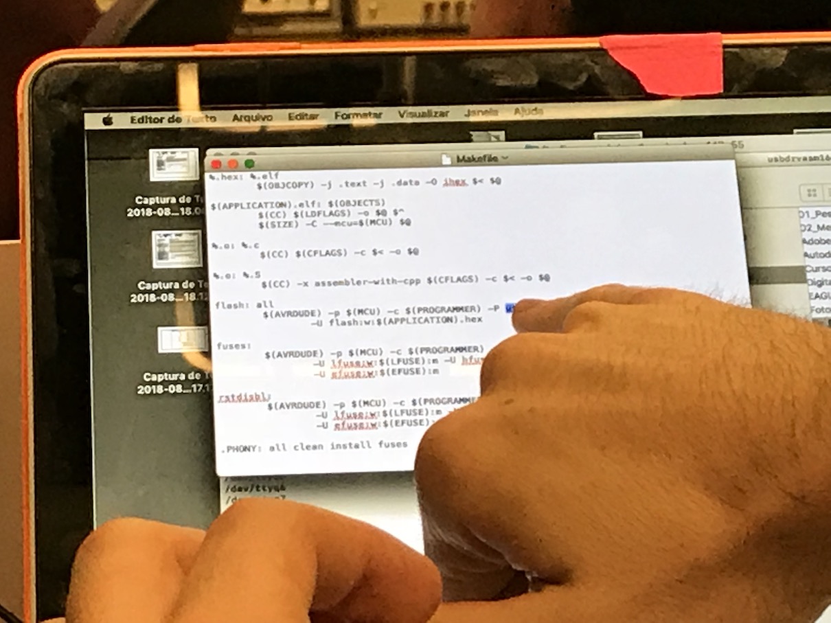
Mac Driver Problem: Macs make it difficult to communicate directly with serial ports. You need to change your permissions. In order to be able to program these on a mac computer you need to enter the following into terminal, in order to change your permissions (you should only need to do this once for your computer in order to be set up):
ls -al /dev/ttyUSB0 ( this last part is specific to the device. You are specifying what device you are trying to change permissions for) sudo usermod -a -G dialout MY_USER_NAME sudo usermod -a -G lpadmin MY_USER_NAME
USB Problems: You (may) run into issues if you are using USB 3.0 or USB C. In order to avoid this, plug in an old USB 2.0 Hub.